
Intelligent pneumatic solid rim lubricating system and lubricating method

A lubricating system and rim technology, which is applied in the field of intelligent pneumatic solid rim lubrication system and rim lubrication, can solve the problems of spring failure, high lubrication cost, and high price of lubricating blocks, and achieve the effect of avoiding excessive lubrication and reducing use

Active Publication Date: 2017-02-08
BEIJING RAILWELD NEW MATERIAL TECH CO LTD +2
View PDF6 Cites 3 Cited by
  • Summary
  • Abstract
  • Description
  • Claims
  • Application Information

AI Technical Summary

Problems solved by technology

[0006] Although the above two schemes are different in structure, they all have the following technical problems: 1. But because they all take the elastic pressure of the spring as the power source, it is impossible to avoid the solid lubricating block being permanently extruded on the wheel rim, 2. During the operation of the rail vehicle, due to the swing and vibration of the wheel, the wheel rim also has a reverse force and collision on the lubricating block; 3. The pressure of the lubricating block on the rim is unstable, even It may be separated from the wheel rim, which will affect the coating effect of the solid lubricant; 4. The solid lubricant device is installed on the rail vehicle bogie. During the operation of the rail vehicle, the bogie and the spring may resonate, causing the spring Ineffective, unable to effectively squeeze the lubricating block to lubricate the wheel rim; 5. The lubricating block with good lubricating effect is expensive in the solid rim lubrication technology, and the lubrication cost is higher due to the full contact between the lubricating block and the wheel rim

Method used


Image

  • Intelligent pneumatic solid rim lubricating system and lubricating method
  • Intelligent pneumatic solid rim lubricating system and lubricating method
  • Intelligent pneumatic solid rim lubricating system and lubricating method

Examples


Embodiment Construction

[0077] The illustrative and non-limiting embodiments of the present invention will be described in detail below with reference to the accompanying drawings, and the intelligent pneumatic solid rim lubrication system and lubrication method according to the present invention will be further described.

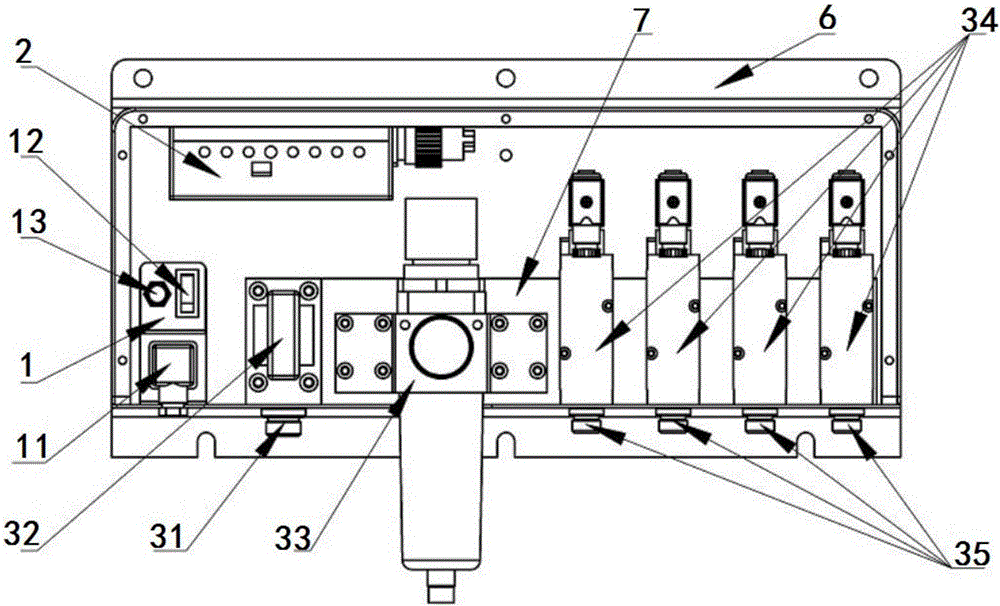
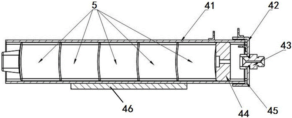
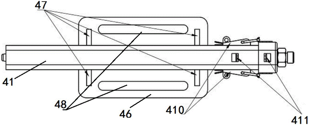
[0078] One aspect of the present invention proposes a kind of intelligent pneumatic solid rim lubricating system, and this system comprises control system and a plurality of lubricating mechanism 4 that is connected with control system (each in a plurality of lubricating mechanism 4 comprises shell, rear cover 42 And the piston 44, wherein the housing includes a cylinder 41). Refer below figure 1 and 2 This intelligent pneumatic solid rim lubrication system is described in detail.

[0079] refer to figure 1 , the control system includes a power supply module 1, an electric controller 2 and a pneumatic actuator 3 (a pneumatic actuator 3 intake joint 31, a cut-off plug 32, a dec...


PUM

PropertyMeasurementUnit
Thicknessaaaaaaaaaa
The inside diameter ofaaaaaaaaaa
Thicknessaaaaaaaaaa

Abstract

The invention discloses an intelligent pneumatic solid rim lubricating system and a lubricating method using the lubricating system. The lubricating system comprises a control system and a plurality of lubricating mechanisms connected with the control system, wherein the control system comprises a power module, an electric controller and a pneumatic actuator; the electric controller is connected with the power module; the pneumatic actuator is connected with the power module; the pneumatic actuator is respectively connected with the electric controller, an external compressed air source and the lubricating mechanisms; the lubricating mechanisms are respectively close to the rim of a railway vehicle; and a lubricating block is contained in each of the lubricating mechanisms. According to the intelligent pneumatic solid rim lubricating system and the lubricating method, the running condition of the railway vehicle can be detected in real time, and a corresponding lubricating strategy can be output, so that the lubricating system has economical efficiency and instantaneity; and the lubricating mechanisms are driven in a pneumatic mode to lubricate the rim, so that the stability is higher.

Description

technical field [0001] The invention relates to the field of rail vehicle rim lubrication, and more specifically, to an intelligent aerodynamic solid rim lubrication system and a rim lubrication method. Background technique [0002] When rail vehicles, bullet trains and urban rail vehicles go through curves or swing in a serpentine shape, severe friction and wear will occur between the wheel rim and the rail gauge angle. One of the main types of damage that seriously affects wheel and rail life. [0003] The flange lubrication technology is an important means to slow down the wear of the flange rail side. Properly lubricating the wheel flange and gauge angle can improve the contact state of the wheel and rail, not only prolong the service life of the wheel and rail, but also reduce the derailment coefficient, benefit driving safety, reduce wheel-rail noise and have a certain energy-saving effect. [0004] According to the form of lubricant, rim lubrication can be divided i...

Claims


Application Information

Patent Timeline
IPC IPC(8): B61K3/02
CPCB61K3/02
Inventor 杨兴宽申灏王冬冬
Owner BEIJING RAILWELD NEW MATERIAL TECH CO LTD
Learn More