
Container boat with cargo loading and unloading functions

A technology for container ships and containers, applied in cargo handling equipment, hulls, ship construction, etc., can solve the problems of high investment cost of container ship terminals, restricting the development of container transportation industry, and single container transportation routes, etc., to achieve stable connection and convenient transportation. , the effect of improving transportation efficiency

Active Publication Date: 2017-02-08
708TH RES INST OF CSSC
View PDF7 Cites 7 Cited by
  • Summary
  • Abstract
  • Description
  • Claims
  • Application Information

AI Technical Summary

Problems solved by technology

[0004] At present, the unloading method of container ships generally relies on professional cranes on the wharf to load and unload containers. Compared with bulk carriers and oil tankers, container ships have more stringent loading and unloading conditions due to problems with placement and fixing. It must be operated at a specific terminal, and the investment cost of professional container ship terminals is high and the payback period is long. Therefore, the number of professional container ship terminals is small, which causes the problem of a single container transportation route, and the containers on the current container ships are made of "boxes". Units, loading and unloading one box at a time, the efficiency is low, which limits the development of the container transportation industry
[0005] To sum up, the current loading and unloading methods of container ships must rely on professional cranes on professional container terminals, and there are problems of small number of professional container terminals and low loading and unloading efficiency

Method used


Image

  • Container boat with cargo loading and unloading functions
  • Container boat with cargo loading and unloading functions
  • Container boat with cargo loading and unloading functions

Examples


Embodiment Construction

[0032] In order to make it easy to understand the technical means, creative features, goals and effects achieved by the present invention, the following examples are combined with the appended figure 1 to attach Figure 11 The technical solutions provided by the present invention are described in detail, but the following content is not intended as a limitation of the present invention.

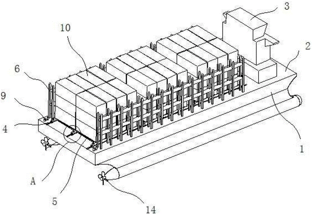
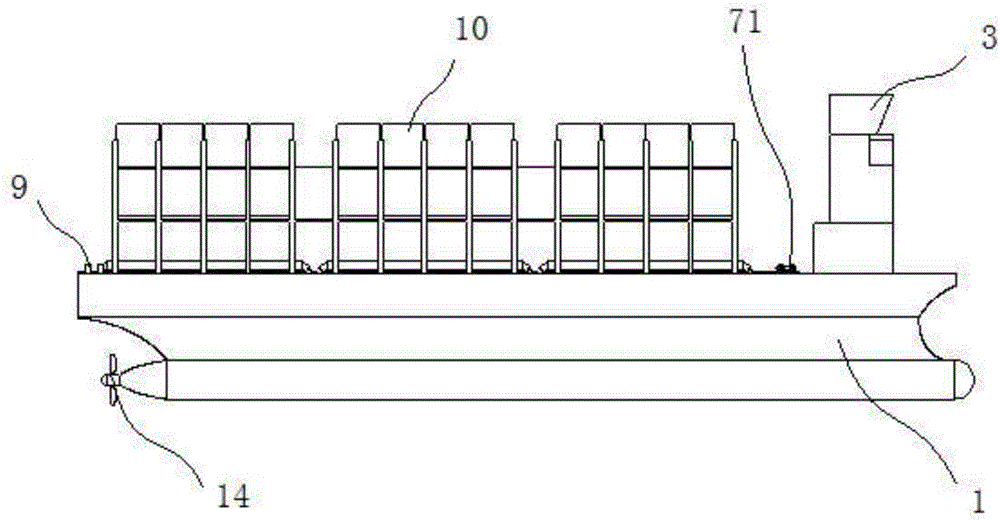
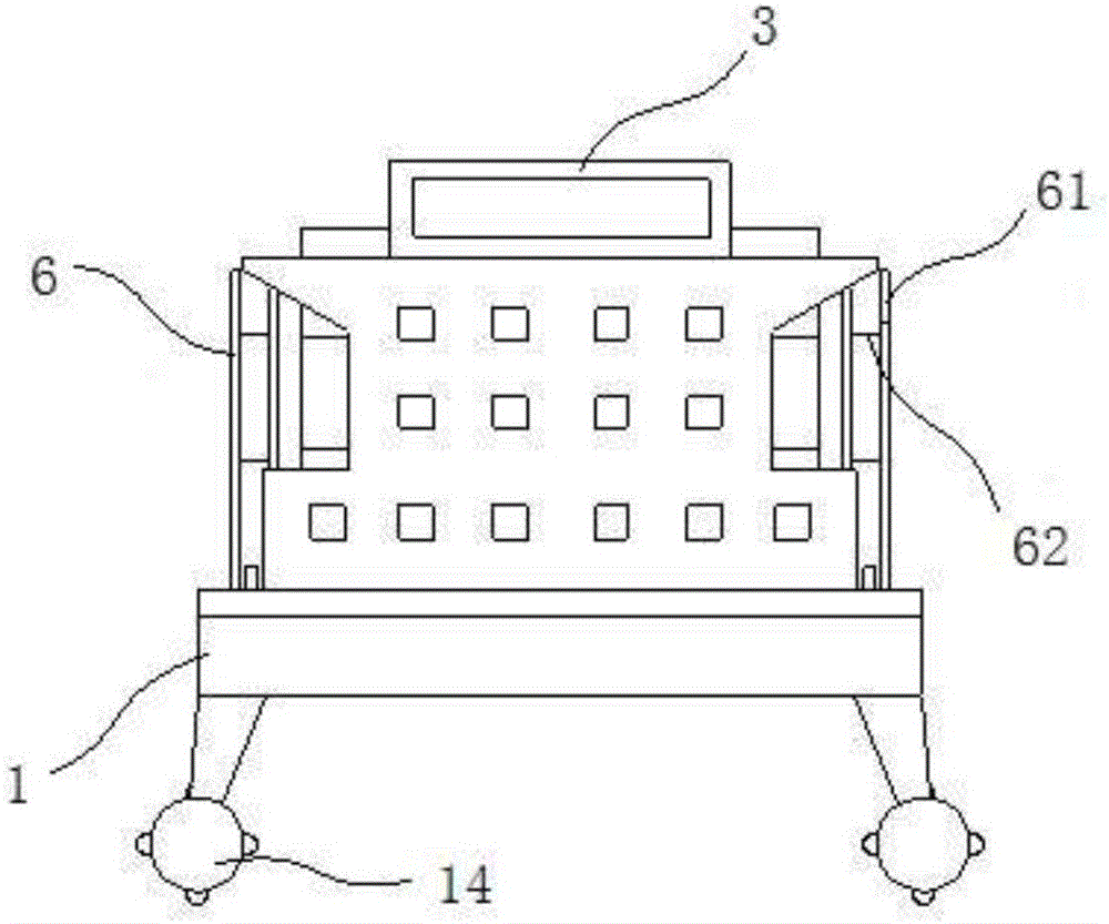
[0033] figure 1 It is a structural diagram of an embodiment of a container ship capable of loading and unloading cargo of the present invention; figure 2 It is a structural diagram of a viewing angle of a preferred embodiment of the present invention; image 3 It is a structural diagram of another perspective of a preferred embodiment of the present invention; Figure 4 It is a structural diagram of another perspective of a preferred embodiment of the present invention. like figure 1 , figure 2 , image 3 as well as Figure 4 As shown, the container ship capable of loading and unloa...


PUM


Abstract

The invention provides a container boat with cargo loading and unloading functions, and belongs to the technical field of boat transportation equipment. The container boat with the cargo loading and unloading functions comprises a boat body, a desk, an upper layer building, a container carrier, a binding bridge and an executer, wherein the upper layer building and the container carrier are arranged on the deck of the boat body; the binding bridge is arranged at the two sides of the deck in the length direction of the boat body; the executer is arranged on the deck positioned between the container carrier and the upper layer building. A rail and a container trolley are used as the container carriers; in addition, a fixed lug plate is arranged beside the rail and is hinged to a fixed hole plate arranged at the container trolley through a shaft pin; the container trolley is temporarily fixed on the deck; the safety is higher; the container trolley is dragged to slide on the rail through a boat winch and a wharf winch; the loading and unloading on the container can be realized; the use of large-scale hoisting equipment is not needed; the loading and the unloading are more convenient; in addition, the containers are loaded and unloaded in a piled form; the loading and unloading efficiency is higher; the pressure of a professional container wharf can be relieved.

Description

technical field [0001] The invention relates to the technical field of ship transportation equipment, in particular to a container ship capable of loading and unloading cargo. Background technique [0002] Today, with the development of global economic integration, the trade ties of various places are getting closer and closer, and goods need to be transported between places. At present, the three major transportation methods of goods include land transportation, sea transportation and air transportation, and sea transportation is the cheapest transportation method. used by traders. [0003] As the main way of shipping, transport ships have become an indispensable part of shipping, and container ships, as the three main forces of transport ships, have won people's favor by virtue of their convenient transportation, high speed and good cargo safety. favor. [0004] At present, the unloading method of container ships generally relies on professional cranes on the wharf to lo...

Claims


Application Information

Patent Timeline
IPC IPC(8): B63B1/12B63B15/00B63B25/22B63B27/00
CPCB63B1/121B63B15/00B63B25/22B63B27/00
Inventor 张志康韩钰邱伟强李丹丹顾俊唐宇
Owner 708TH RES INST OF CSSC
Learn More