Motor angle control method, system and unmanned aerial vehicle

An angle control and controller technology, applied in the field of aircraft, can solve problems such as poor control accuracy, complex control process, and unsatisfactory control effect, and achieve the effect of improving control accuracy and concise control process.

Active Publication Date: 2019-02-19
ZEROTECH (SHENZHEN) INTELLIGENCE ROBOT CO LTD
View PDF4 Cites 0 Cited by
  • Summary
  • Abstract
  • Description
  • Claims
  • Application Information

AI Technical Summary

Problems solved by technology

[0003] When using a sensory brushless DC motor to control the angle of the pan / tilt, the control accuracy is related to the structure of the position sensor and the sensory brushless DC motor, and the control process is more complicated; when using a steering gear to control the angle of the pan / tilt, the control accuracy is relatively Poor, unsatisfactory control effect

Method used


Image

  • Motor angle control method, system and unmanned aerial vehicle
  • Motor angle control method, system and unmanned aerial vehicle
  • Motor angle control method, system and unmanned aerial vehicle

Examples


Embodiment Construction

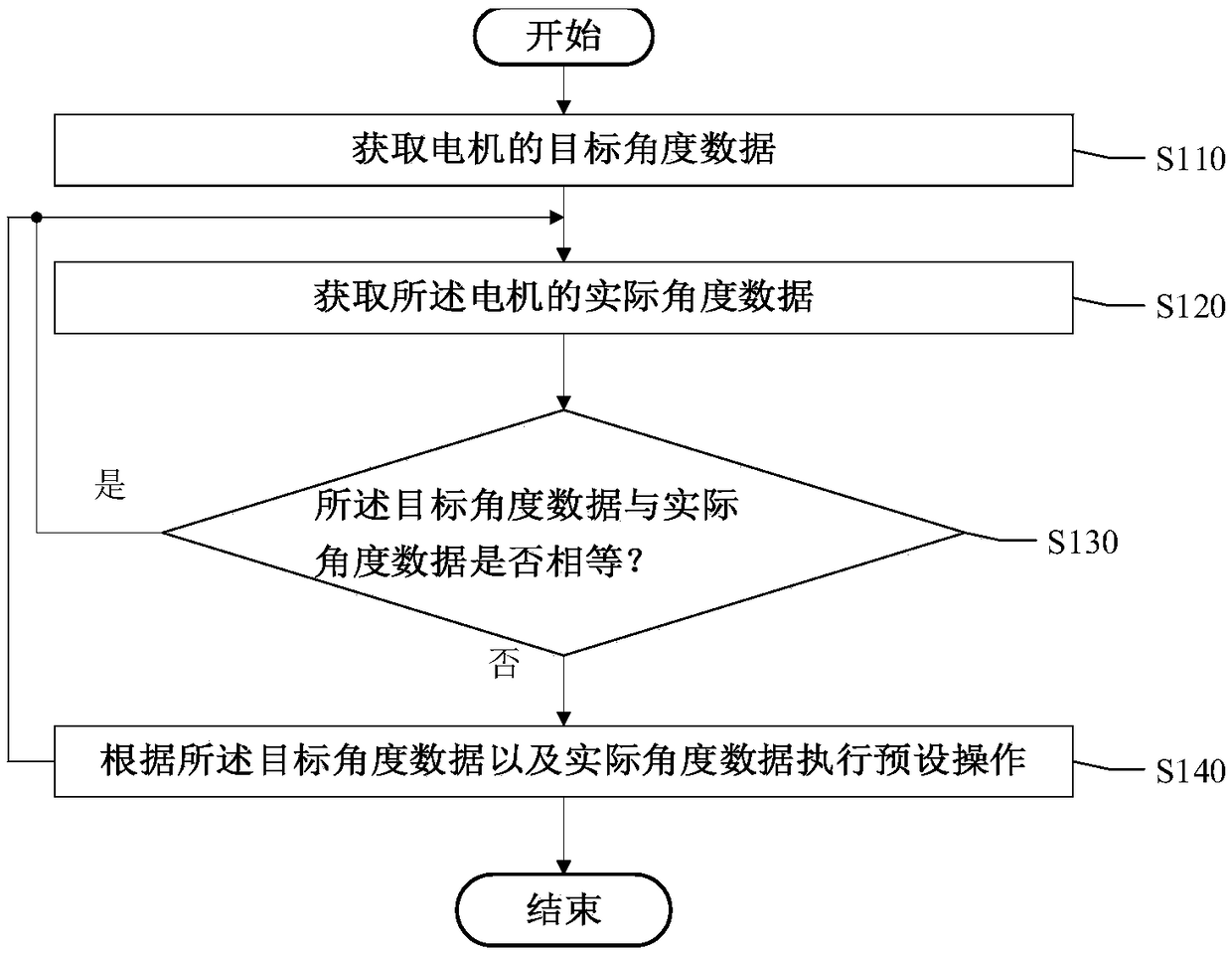
[0018] The following will clearly and completely describe the technical solutions in the embodiments of the present invention with reference to the accompanying drawings in the embodiments of the present invention. Obviously, the described embodiments are only some of the embodiments of the present application, not all of them. The following detailed description of the embodiments of the application provided in the accompanying drawings is not intended to limit the scope of the claimed application, but merely represents selected embodiments of the application. Based on the embodiments of the present application, all other embodiments obtained by those skilled in the art without making creative efforts belong to the scope of protection of the present application.

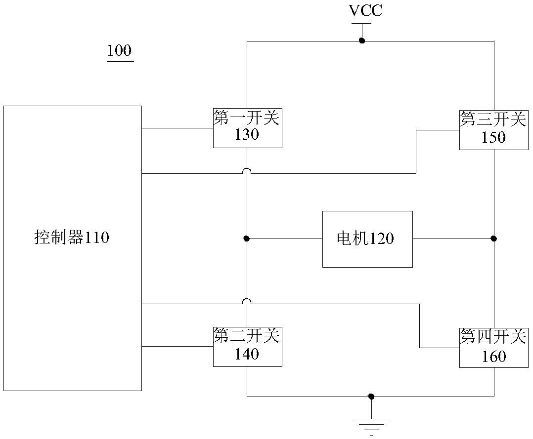
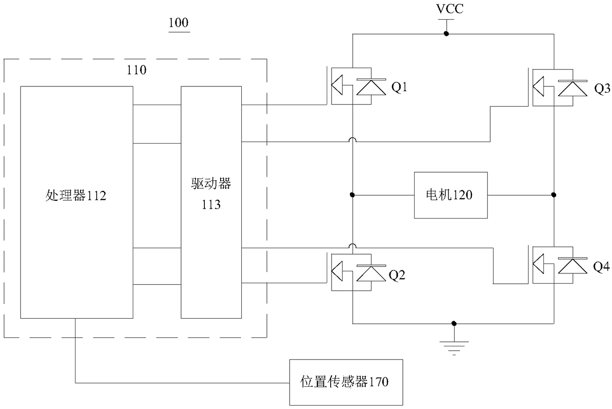
[0019] See figure 1 , figure 1 It is a schematic diagram of the composition of the motor angle control system 100 provided by the embodiment of the present invention. The motor angle control system 100 is applied to...


PUM


Abstract

A motor angle control method provided by an embodiment of the invention comprises the following steps: a controller acquires the target angle data of a motor and the actual angle data of the motor; the controller judges whether the target angle data and the actual angle data are equal; and if the target angle data and the actual angle data are not equal, the controller processes the target angle data and the actual angle data, and switches on a first path coupled to the motor to make the motor rotate forwardly or switches on a second path coupled to the motor to make the motor rotate reversely according to the processing result. According to the motor angle control method, a motor angle control system and an unmanned aerial vehicle provided by the embodiments of the invention, the first path or the second path coupled to the motor can be controlled according to the values of the target angle data and the actual angle data of the motor so as to realize forward or reverse rotation of the motor. Compared with the existing motor angle control method, the control process is simple, and the precision of motor control is improved.

Description

technical field [0001] The present application relates to the field of aircraft technology, in particular, to a motor angle control method, system and unmanned aerial vehicle. Background technique [0002] With the development of the UAV industry, the technology for controlling UAV gimbal is becoming more and more mature. At present, there are two ways to control the angle of the pan / tilt. One is to realize the closed-loop control of the angle of the pan / tilt with the sensory brushless DC motor and the position sensor, that is, the position sensor obtains the rotor position information of the sensory brushless DC motor and sends it To the controller, so that the controller controls every two phases of the three-phase stator windings in the sensory brushless DC motor according to the rotor position information, so as to adjust the speed and rotation direction of the sensory brushless DC motor; the other is based on The steering gear cooperates with the position sensor to rea...

Claims


Application Information

Patent Timeline
Patent Type & Authority Patents(China)
IPC IPC(8): H02P7/03
Inventor 林帅杨建军
Owner ZEROTECH (SHENZHEN) INTELLIGENCE ROBOT CO LTD
Why Eureka
Try Eureka