
Automatic paint spraying device

A paint spray gun and installation groove technology, which is applied in the field of automatic machining, can solve the problems of high labor cost, low efficiency and high precision requirements.

Inactive Publication Date: 2017-02-15
LANTEX WINDOW FASHIONS CO LTD
View PDF5 Cites 10 Cited by
  • Summary
  • Abstract
  • Description
  • Claims
  • Application Information

AI Technical Summary

Problems solved by technology

[0004] The PCB circuit board is the most basic accessory in the electronics industry. The PCB circuit board is integrated with a complete set of circuit structures, and a number of jacks are reserved. The pins of various electronic components are inserted into the jacks to connect to the circuit; After the electronic components are inserted into the jack, they need to be connected to the PCB board through soldering; after the soldering is completed, it is necessary to dispense glue or spray paint on the pins and the jack to fix the electronic components, and at the same time protect and insulate the connection between the pins and the jack position; affected by the volume and installation position of electronic components, the precision of dispensing or painting is high. The existing dispensing or painting action is usually directly on the connection between the pin and the socket through a hand-held glue gun or paint spray gun. The dispensing / painting process has low efficiency and high labor costs, and is not suitable for modern industrial production

Method used


Image

  • Automatic paint spraying device
  • Automatic paint spraying device
  • Automatic paint spraying device

Examples


Embodiment Construction

[0031] The present invention will be further described below in conjunction with the accompanying drawings:

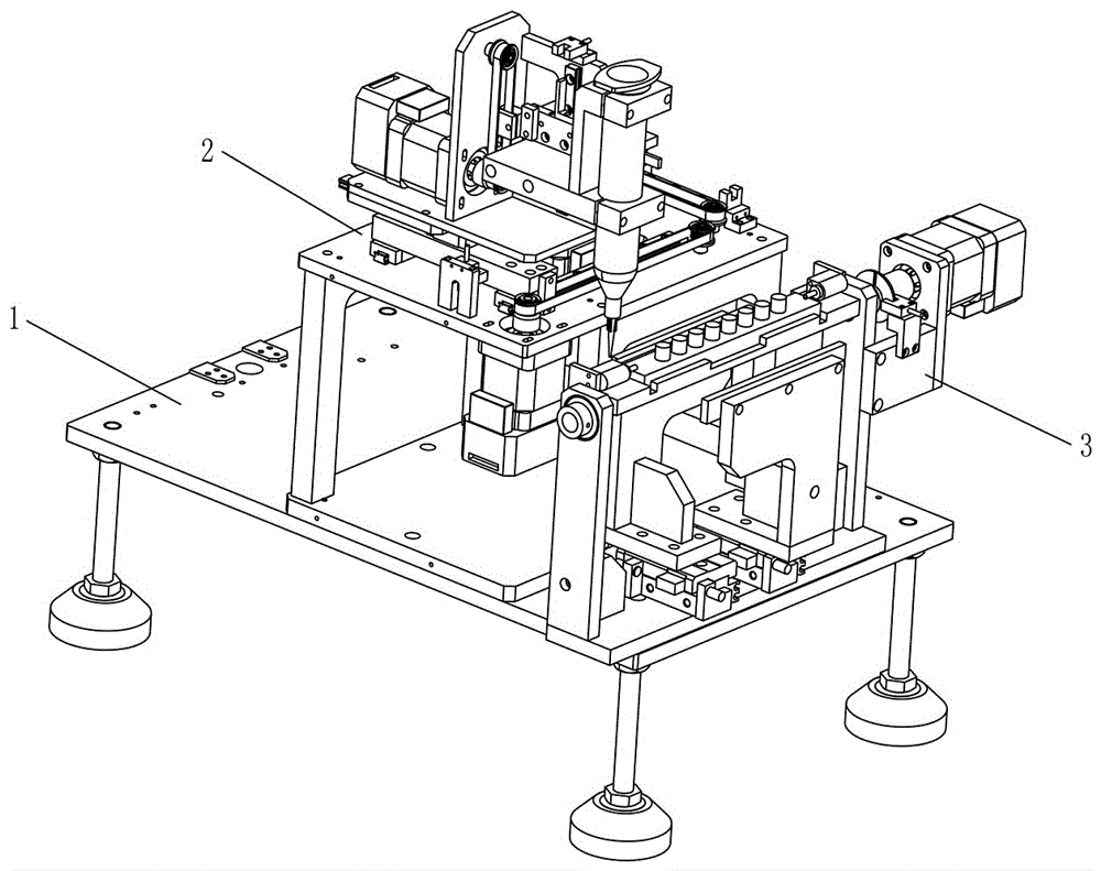
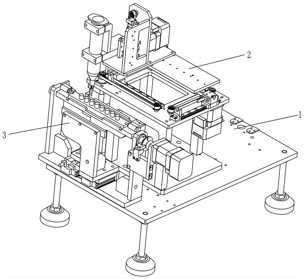
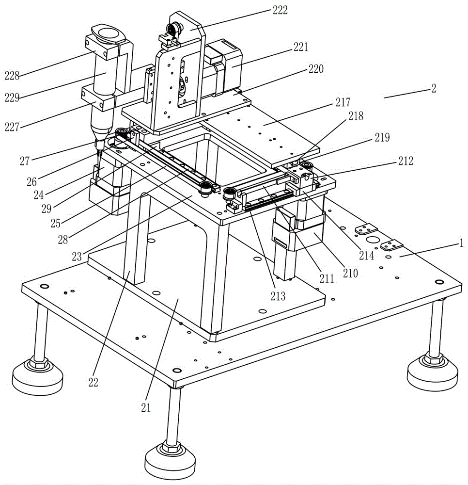
[0032] like Figure 1 to Figure 9 As shown, the technical solution adopted by the present invention is as follows, an automatic paint spraying device, comprising a base plate 1, a product fixing mechanism 3 and a paint spraying mechanism 2 arranged on the base plate 1, wherein the above-mentioned base plate 1 is horizontally arranged, and the product fixing mechanism 2 is fixedly arranged On one side of the base plate 1, the product fixing mechanism 2 includes a product supporting component and a product rotating component. The product 310 to be painted is detachably placed on the product supporting component. The product rotating component is arranged on one side of the product supporting component and is connected with the product supporting component. The components are connected, so that the product 310 can be rotated to adjust the spraying angle by driving the pro...


PUM


Abstract

The invention discloses an automatic paint spraying device. The automatic paint spraying device comprises a base plate, a product fixing mechanism and a paint spraying mechanism, wherein the product fixing mechanism and the paint spraying mechanism are arranged on the base plate. The base plate is arranged horizontally. The product fixing mechanism is fixedly arranged on one side of the base plate and comprises a product supporting assembly and a product rotating assembly. A product to be sprayed with paint is detachably placed on the product supporting assembly. The product rotating assembly is arranged at one side of the product supporting assembly and connected with the product supporting assembly. The paint spraying mechanism is arranged at one side of the product supporting assembly and comprises a paint spraying horizontal-driving assembly, a paint spraying lifting-driving assembly and a paint spraying gun. The paint spraying horizontal-driving assembly is arranged on the base plate, and the paint spraying lifting-driving assembly is connected to the paint spraying horizontal-driving assembly. The paint spraying gun is connected to the paint spraying lifting-driving assembly and driven by the paint spraying lifting-driving assembly to rise and fall to move onto the product, so that automatic paint spraying of the product is conducted. By adoption of the automatic paint spraying device, efficient and high-precision automatic paint spraying is achieved, and the production cost is effectively reduced.

Description

technical field [0001] The invention relates to the field of automatic mechanical processing, in particular to an automatic paint spraying device. Background technique [0002] Paint or coating is a chemical mixture coating that can be firmly covered on the surface of objects for protection, decoration, marking and other special purposes. As a kind of coating, paint can be applied to the surface of the object by different construction techniques to form a solid film with firm adhesion, certain strength and continuity; the film formed in this way is generally called a coating film, also known as a paint film or a coating. Coatings are generally composed of film-forming substances, fillers (pigments and fillers), solvents, and additives. They belong to organic chemical polymer materials, and the formed coating film belongs to the type of polymer compounds. According to the classification of modern chemical products, coatings It belongs to fine chemical products; modern coatin...

Claims


Application Information

Patent Timeline
Patent Type & Authority Applications(China)
IPC IPC(8): B05B13/04B05B13/02B05B15/08B05B15/68
CPCB05B13/02B05B13/0242B05B13/041B05B15/68
Inventor 吴姣
Owner LANTEX WINDOW FASHIONS CO LTD
Learn More