Positioning mounting seat for piston oiling, rotating positioning mounting seat, piston oiling method

A technology of positioning installation and mounting seat, which is applied to the device and coating of the surface coating liquid, which can solve the problems of unstable grip, low work efficiency, and labor consumption, so as to save oiling time and improve oiling efficiency. Effect, solve the effect of unstable grip

Inactive Publication Date: 2019-05-17
ANHUI HIGH TECH POWER TECH
View PDF6 Cites 0 Cited by
  • Summary
  • Abstract
  • Description
  • Claims
  • Application Information

AI Technical Summary

Problems solved by technology

[0005] The above manual oiling has the following disadvantages: (1) the uniformity of oiling is not easy to control; (2) the work efficiency is low, not only time-consuming, but also labor-intensive; (3) if the brush is dipped in too much lubricating oil, it will During the process, the lubricating oil is easy to drip on the staff, which is inconvenient for later cleaning; (4) When one side of the piston is coated with lubricating oil, the staff needs to hold the side of the piston that is coated with lubricating oil. The other side of the piston is then oiled; from this, there may be problems with less stable grip due to less grip friction

Method used


Image

  • Positioning mounting seat for piston oiling, rotating positioning mounting seat, piston oiling method
  • Positioning mounting seat for piston oiling, rotating positioning mounting seat, piston oiling method
  • Positioning mounting seat for piston oiling, rotating positioning mounting seat, piston oiling method

Examples


Embodiment 1

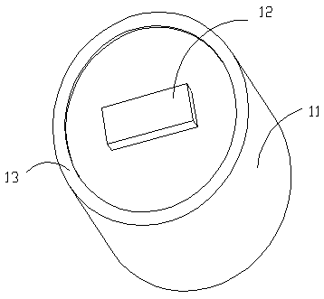
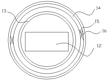
[0027] Such as figure 1 , 2 , 3, the present embodiment discloses a positioning mounting seat for piston oiling, including a bottom mounting seat 11 and an upper mounting seat 12. The upper mounting base 12 is arranged above the bottom mounting base 11 and is detachably connected with the upper mounting base 12 . The edge of the top of the bottom mounting seat 11 is provided with a protrusion 13 that is adapted to the shape of the piston stop to be oiled. The distance between the two ends of the upper mounting seat 12 in the length direction is equal to or slightly smaller than the distance between the two pin-hole seats in the piston to be oiled.

[0028] In this embodiment, the piston to be oiled is placed on the positioning mounting seat, so that the stop of the piston to be oiled is limited on the protrusion 13 at the top edge of the positioning mounting seat, so that the upper mounting seat 12 of the positioning mounting seat is limited. Located between the two pin-hol...

Embodiment 2

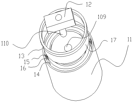
[0039] Such as figure 1 , 2 , Shown in 3, a kind of piston oiling is used rotation positioning mounting seat, comprises bottom mounting seat 11, upper mounting seat 12, motor. The motor is arranged under the bottom mounting base 11, and the bottom mounting base 11 is connected with the output shaft of the motor. The upper mounting base 12 is arranged above the bottom mounting base 11 and is detachably connected with the upper mounting base 12 . The edge of the top of the bottom mounting seat 11 is provided with a protrusion 13 that is adapted to the shape of the piston stop to be oiled. The distance between the two ends of the length direction of the upper mounting seat 12 is equal to or slightly smaller than the distance between the two pin-hole seats in the piston to be oiled.

[0040] In some embodiments: the bottom of the bottom mounting seat is provided with a mounting groove, and a rubber sleeve is sleeved in the mounting groove, and the output shaft of the motor is i...


PUM


Abstract

The invention discloses a positioning mounting base for piston oiling. The positioning mounting base for piston oiling comprises a bottom mounting base body and an upper mounting base body. The upper mounting base body is arranged on the bottom mounting base body and detachably connected with the upper mounting base body. A protrusion which is matched with a stop notch of a piston to be oiled in shape is arranged on the edge of the top of the bottom mounting base body. The distance between the two ends, in the length direction, of the upper mounting base body is equal to or slightly smaller than the distance between two pin hole seats in the piston to be oiled. The invention further discloses a rotary positioning mounting base for piston oiling and a piston oiling method. The positioning mounting base and rotary positioning mounting base for piston oiling and the piston oiling method have the advantages that the piston is mounted stably and firmly, oiling is uniform, and the oiling efficiency is high.

Description

technical field [0001] The invention relates to the technical field of piston oiling, in particular to a positioning mounting seat for piston oiling, a rotation positioning mounting seat and a piston oiling method. Background technique [0002] The piston can be mainly divided into three parts: the piston crown, the piston head and the piston skirt. The main function of the piston is to withstand the combustion pressure in the cylinder and transmit this force to the crankshaft through the piston pin and connecting rod. [0003] The top of the piston is an integral part of the combustion chamber, so it is often made into different shapes. The top of the gasoline engine piston is mostly flat or concave, so that the structure of the combustion chamber is compact, the heat dissipation area is small, and the manufacturing process is simple. The piston head is the part above the piston pin seat. Piston rings are installed on the piston head to prevent high-temperature and high-pr...

Claims


Application Information

Patent Timeline
Patent Type & Authority Patents(China)
IPC IPC(8): B05C13/02B05C1/06B05D1/28
CPCB05C1/06B05C13/02B05D1/28
Inventor 章高伟蓝天赵森林唐俊林刘杰
Owner ANHUI HIGH TECH POWER TECH
Why Eureka
Try Eureka