Supercharge Your Innovation With Domain-Expert AI Agents!

Stripper plate structure capable of punching several tens of thousands of products and method thereof

A technology for stripping plates and products, which is applied in the direction of manufacturing tools, metal processing equipment, stripping devices, etc., can solve the problems of difficult alignment gaps and low life of stamping die structures, and achieve simple structure, reduced processing life, and reduced thickness Effect

Inactive Publication Date: 2017-02-15
FUZHOU UNIV
View PDF5 Cites 0 Cited by
  • Summary
  • Abstract
  • Description
  • Claims
  • Application Information

AI Technical Summary

Problems solved by technology

[0003] The present invention improves the above problems, that is, the technical problem to be solved by the present invention is that the existing stamping die structure is difficult to align the gap and the life is low

Method used


Image

  • Stripper plate structure capable of punching several tens of thousands of products and method thereof
  • Stripper plate structure capable of punching several tens of thousands of products and method thereof
  • Stripper plate structure capable of punching several tens of thousands of products and method thereof

Examples


Embodiment Construction

[0014] The present invention will be described in further detail below in conjunction with the accompanying drawings and specific embodiments.

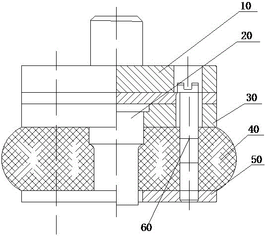
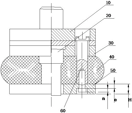
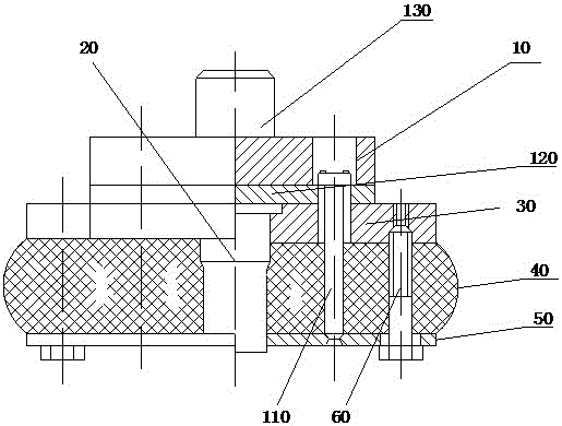
[0015] Such as Figure 3-4 As shown, a stripping plate structure capable of punching tens of thousands of products includes an upper template 10, a punch fixing plate 30, a rubber pad 40 and a stripping plate 50 arranged sequentially from top to bottom. The upper template 10 There is a guide post 110 running through the stripping plate, and a punch 20 is provided in the middle of the upper template 10. The punch fixing plate 30, the rubber pad 40 and the middle of the stripping plate 50 have a through hole for the punch to pass through, and the punch is fixed. Both sides of the plate, the rubber pad and the stripper plate are provided with a flange portion 510 protruding from the outer side of the upper formwork, and the flange portion is provided with a bolt hole for the bolt to pass through. During the trial punching operation, the ...


PUM


Abstract

The invention provides a stripper plate structure capable of punching several tens of thousands of products and a method thereof. The stripper plate structure comprises an upper die plate, a male die fixing plate, a rubber mat and a stripper plate which are sequentially arranged from top to bottom. A guide pillar penetrates through the stripper plate from the upper die plate. A male die is arranged in the middle of the upper die plate. The middle of the male die fixing plate, the middle of the rubber mat and the middle of the stripper plate are provided with through holes allowing the male die to penetrate through. The two sides of the male die fixing plate, the two sides of the rubber mat and the two sides of the stripper plate are all provided with flange parts which protrude towards the outer side of the upper die plate. The male die fixing plate, the rubber mat and the stripper plate are provided with connecting bolts penetrating through the corresponding flange parts. The stripper plate structure is simple in structure. Due to the fact that the two sides of the male die fixing plate, the two sides of the rubber mat and the two sides of the stripper plate are all provided with the flange parts which protrude towards the outer side of the upper die plate, bolts need to be used for pre-fixing the stripper plate during gap alignment. The die thickness can be decreased due to the design of the flange parts, and the phenomena that the thickness of the stripper plate is increased and the processing service life of the male die is shortened for the reason that the fixing mode with the unified connecting and guiding functions is used for design are avoided.

Description

technical field [0001] The invention relates to a stripping plate structure capable of punching tens of thousands of products and a method thereof. Background technique [0002] Such as figure 1 and figure 2 As shown, the structure is designed for the existing stamping die, figure 1 The middle is the mold structure used in sheet metal blanking production, especially in large-area sheet metal blanking processing. The mold structure mainly includes upper template 10, punch 20, punch fixing plate 30, rubber pad 40, plate 50 and the connecting bolts 60 used to lock the various components when aligning the gap during the mold trial process, the connecting bolts 60 can directly fix the rubber pad 40 and the stripper plate 50 during the mold trial, figure 1 There is no guide die in this structure, and it is difficult to align the gap during installation. figure 2 It is another form of connection structure, in which the connecting bolt 60 is reversely locked by the lower part ...

Claims


Application Information

Patent Timeline
IPC IPC(8): B21D28/14B21D45/08
CPCB21D28/14B21D45/08
Inventor 陈功振
Owner FUZHOU UNIV
Features
  • R&D
  • Intellectual Property
  • Life Sciences
  • Materials
  • Tech Scout
  • Unparalleled Data Quality
  • Higher Quality Content
  • 60% Fewer Hallucinations
Learn More