Punching die

A punching and die technology, used in punching tools, manufacturing tools, metal processing equipment, etc., can solve problems such as complex die, and achieve the effect of simple structure and convenient use.

Inactive Publication Date: 2017-02-15
ANHUI JIANGHUAI AUTOMOBILE GRP CORP LTD
View PDF5 Cites 3 Cited by
  • Summary
  • Abstract
  • Description
  • Claims
  • Application Information

AI Technical Summary

Problems solved by technology

[0005] The invention provides a punching die, in order to solve the problem that the die is relatively complicated when punching a few-shaped parts in the prior art

Method used


Image

  • Punching die
  • Punching die
  • Punching die

Examples


Embodiment Construction

[0029] In order to enable those skilled in the art to better understand the technical solutions of the present invention, the present invention will be further described in detail below in conjunction with the accompanying drawings.

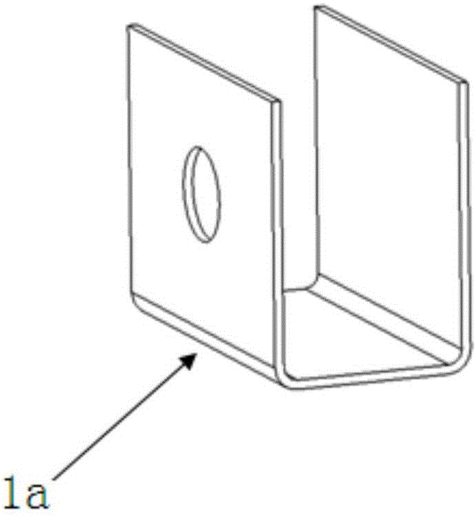
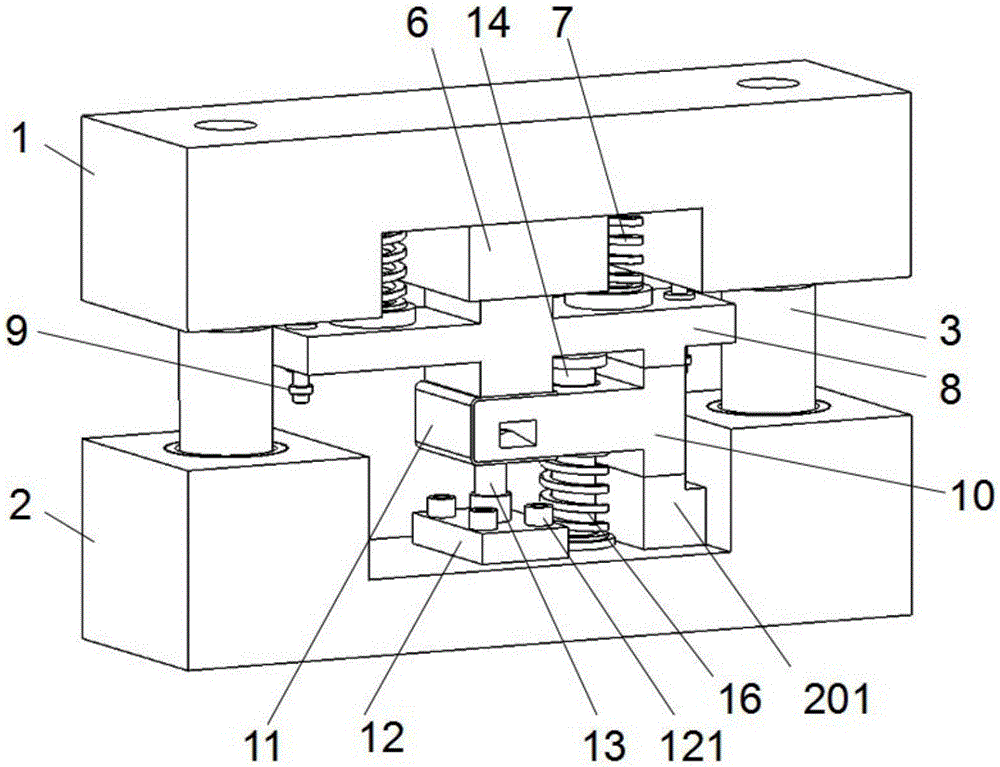
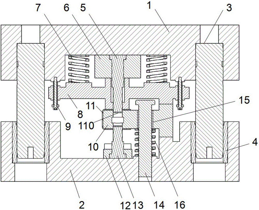
[0030] combine figure 2 image 3 and Figure 9 As shown, it is a punching die provided by the embodiment of the present invention, which is used for punching a few-shaped parts 11, including:

[0031] The lower mold holder 2 is used to carry the related working components of the lower mold, and the upper mold holder 1 is used to carry the related working components of the upper mold.

[0032] The upper fixed block 6 is fixed on the bottom surface of the upper die base 1, and the upper punch 5 is installed on it, and the lower fixed block 12 is installed on the top surface of the lower die base, and the lower punch is installed on it, and the upper fixed block 6 There are stepped holes with different diameters in the upper machining, the diame...


PUM


Abstract

The invention discloses a punching die which is punching holes in a part shaped like a Chinese character 'ji'. The punching die comprises a lower die base, an upper die base, an upper fixing block and a lower fixing block, wherein the upper fixing block is fixed to the bottom face of the upper die base, and provided with an upper punching head, and the lower fixing block is installed on the top face of the lower die base and provided with a lower punching head; the punching die further comprises a punching female die which is of a T-shaped structure, and the punching female die comprises a head and a fixing part horizontally extending out along the middle of the head; and the head is vertically installed on the lower die base, the fixing part is suspended between the upper punching head and the lower punching head, and a guide hole is formed in the fixing part. According to the scheme, the punching female die is of the T-shaped structure, the part shaped like the Chinese character 'ji' is matched with the punching female die, the upper die base drives the upper punching head to downwards move, and punching of the part shaped like the Chinese character 'ji' is achieved. The punching die is simple in structure and convenient to use.

Description

technical field [0001] The invention relates to the field of stamping devices, in particular to a punching die. Background technique [0002] In the production process of stamping parts, when the parts need to be punched, a pair of punching dies need to be designed separately to complete the processing of the holes on the parts. The traditional punching die structure includes upper die base, pressing core, punch, punching die, lower die base, etc. When encountering a shape such as figure 1 For semi-closed parts with the word "几", when the punching position is on the side wall of the part, side punching processing is required, and a wedge device is added, which makes the structure of the punching die complex, and the difficulty of installation and debugging increases. The time period grows. Especially when the hole size of some parts needs to be changed in design, punches and punching dies need to be processed, and repeated research and processing are required. [0003] Th...

Claims


Application Information

Patent Timeline
IPC IPC(8): B21D28/34
CPCB21D28/34
Inventor 徐肖黄涛井芊高双明李杭王旭
Owner ANHUI JIANGHUAI AUTOMOBILE GRP CORP LTD
Why Eureka
Try Eureka