Supercharge Your Innovation With Domain-Expert AI Agents!

A light energy processing device and processing method thereof

A processing device and processing method technology, applied in metal processing equipment, optics, condensing mirrors, etc., can solve the problems of low temperature, difficulty in transmission and reuse of concentrated light energy, improve optical density, and meet the requirements of mechanical processing or metal processing. requirements, the effect of temperature increase

Active Publication Date: 2018-05-25
朱光波
View PDF7 Cites 0 Cited by
  • Summary
  • Abstract
  • Description
  • Claims
  • Application Information

AI Technical Summary

Problems solved by technology

[0005] The main purpose of the present invention is to propose a light energy processing device and its processing method to solve the technical problems of low temperature, convergence degree and difficulty in light energy transmission and reuse in the above-mentioned prior art

Method used


Image

  • A light energy processing device and processing method thereof
  • A light energy processing device and processing method thereof
  • A light energy processing device and processing method thereof

Examples


Embodiment 1

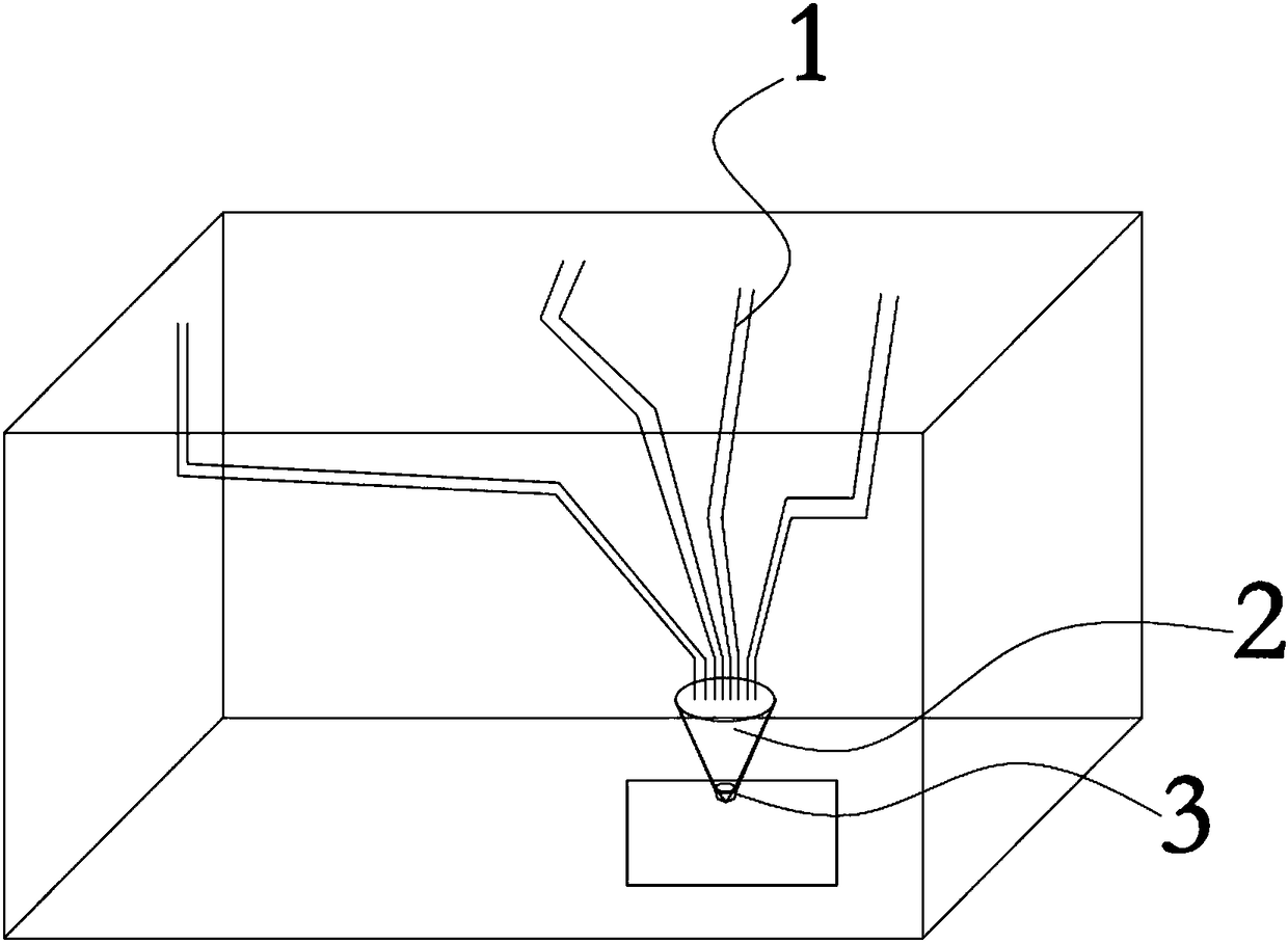
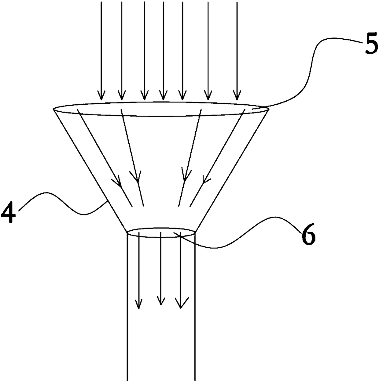
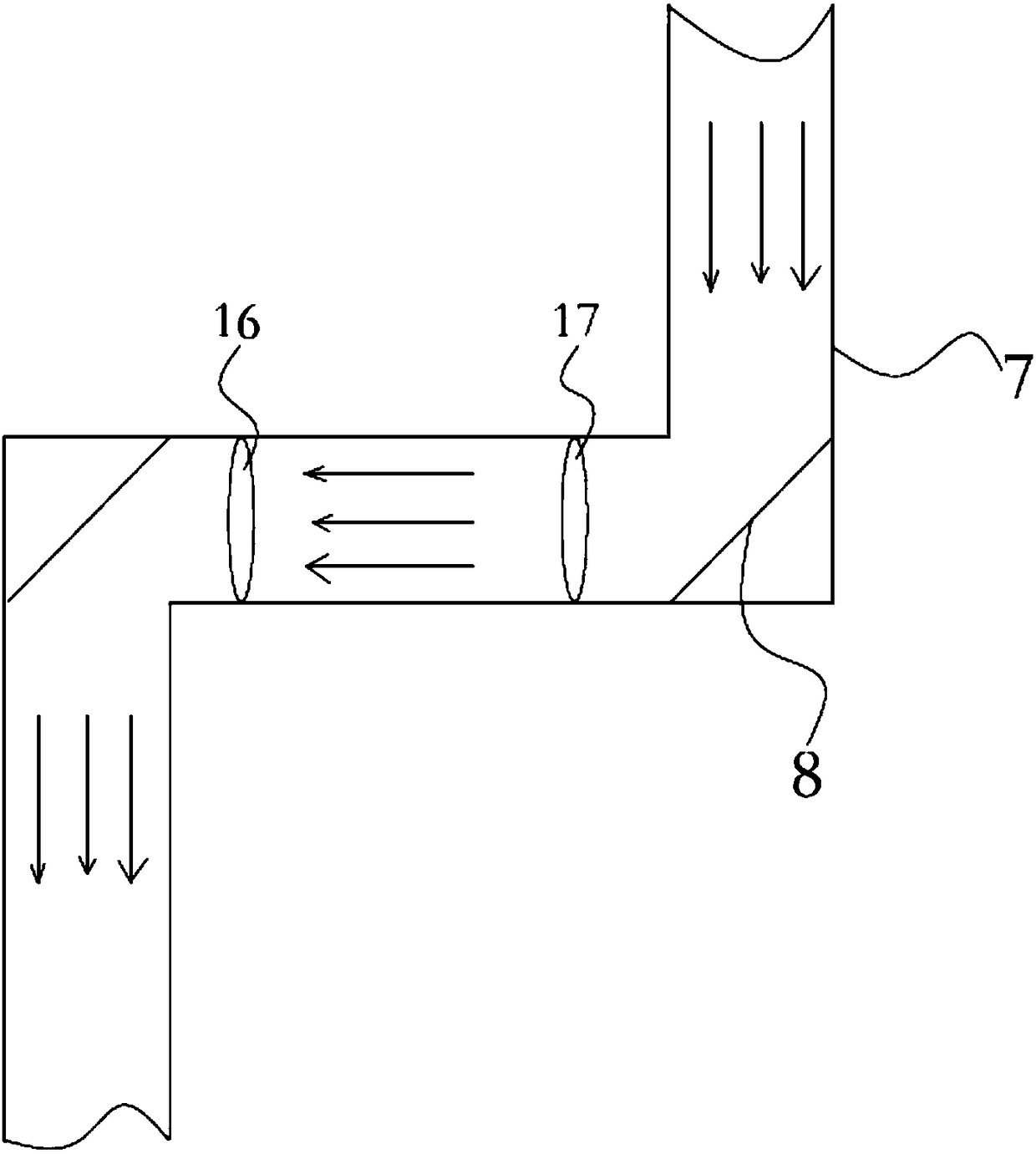
[0035] This embodiment proposes a light energy processing device, including a light energy module, the light energy module includes a lighting mechanism, a light collecting mechanism 2 and a working head 3, the lighting mechanism includes a plurality of light guide tubes 1, the A plurality of light pipes 1 include a tube body 7, and a lighting lens group and a transmission lens group 8 arranged on the tube body 7, and the lighting lens group is arranged at the collection end 4 of the tube body 7 for collecting For light energy, the transmission lens group 8 is arranged inside the tube body 7 for changing the transmission direction of light. The lens group, the light concentrating mechanism 2 is arranged below the output end 9 of the tube body 7, and the output ends 9 of a plurality of the light guide tubes 1 are vertically and evenly arranged in an array above the light concentrating lens group, The working head 3 is arranged on the light concentrating body 12 for converging t...

Embodiment 2

[0044] This embodiment proposes a light energy processing method, using the above light energy processing device to carry out light energy processing, such as Image 6 shown, including the following steps:

[0045] S1. The lighting mechanism collects light energy, gathers and converts the light energy, and transmits the collected light energy to the collection end of the light guide tube;

[0046] S2. Through the transmission lens group in the light guide tube, the light energy is transmitted in the tube body to the nozzle 10 of the output end, and a light spot is projected;

[0047] S3. A plurality of light pipes arranged in a uniform array vertically project a plurality of light spots output to the nozzle 10 onto the condenser lens group of the light-condensing mechanism, and focus the multiple light spots through the condenser lens group , forming a focal point in the concentrating body;

[0048] S4. The focal spot is output from the working head for processing.

[0049]...


PUM


Abstract

The invention discloses an optical energy processing device and a processing method thereof. The optical energy processing device comprises an optical energy module. The optical energy module comprises a lighting mechanism, a light condensation mechanism and a work head. The lighting mechanism comprises a plurality of light guide pipes. The multiple light guide pipes comprise pipe bodies, lighting lens sets and transmitting lens sets. The lighting lens sets and the transmitting lens sets are arranged on the pipe bodies. The lighting lens sets are arranged on the collection ends of the pipe bodies and used for collecting optical energy. The transmitting lens sets are arranged in the pipe bodies and used for changing the transmitting direction of light. The light condensation mechanism comprises a light condensation body and a light condensation lens set arranged in the light condensation body. The light condensation mechanism is arranged below the output ends the pipe bodies. The output ends of the multiple light guide pipes are arranged above the light condensation lens set perpendicularly and evenly in an array mode and used for condensing light output by the multiple light guide pipes. The work head is arranged on the light condensation body. The optical energy processing device and the processing method thereof have the advantages that the light spot temperature is high, and convenient transmitting and recycling are achieved.

Description

technical field [0001] The invention relates to the technical field of light energy processing, in particular to a light energy processing device and a processing method thereof. It is suitable for automatic control of precision machining or integrated optical, mechanical and electrical processing devices, laser processing machinery and devices, and optical parts processing. Background technique [0002] Strong light source energy (natural light) is a kind of clean energy, which is inexhaustible and will not cause environmental pollution. There are more and more strong light source energy products, such as strong light source energy street lamps, strong light source energy traffic lights, strong light source energy Light source energy mobile phone, strong light source energy charger, strong light source energy remote control, strong light source energy water heater, strong light source energy power station, etc., strong light source energy technology has entered people's dai...

Claims


Application Information

Patent Timeline
Patent Type & Authority Patents(China)
IPC IPC(8): B23K26/064G02B19/00
CPCB23K26/064B23K26/0648G02B19/0028G02B19/0042
Inventor 朱光波
Owner 朱光波
Features
  • R&D
  • Intellectual Property
  • Life Sciences
  • Materials
  • Tech Scout
  • Unparalleled Data Quality
  • Higher Quality Content
  • 60% Fewer Hallucinations
Learn More