Laser drilling waste collecting mechanism

A laser drilling machine and waste collection technology, which is applied in laser welding equipment, welding equipment, metal processing equipment, etc., can solve the problems of damage to the optical system, waste material inhalation, poor safety, etc., to ensure normal operation, cleanliness, and reduce effect of influence

Active Publication Date: 2017-02-15
郑招才
View PDF5 Cites 9 Cited by
  • Summary
  • Abstract
  • Description
  • Claims
  • Application Information

AI Technical Summary

Problems solved by technology

[0005] Existing laser cutting devices only perform laser cutting when processing parts. During the processing, some waste materials such as smoke, dust and processing residues will be attached to the surface of the lens and the workpiece, which affects the processing quality of the workpiece and pollutes the In severe cases, the lens will be burned and the optical system will be damaged
[0006] Therefore, it is necessary to remove waste materials such as smoke, dust and processing residues after processing in time. The existing waste materials are generally processed manually, which is easy to inhale the waste materials, which affects health and poor safety.

Method used


Image

  • Laser drilling waste collecting mechanism
  • Laser drilling waste collecting mechanism
  • Laser drilling waste collecting mechanism

Examples


Embodiment Construction

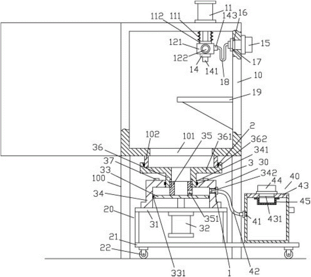
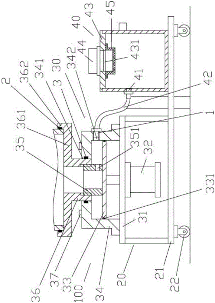
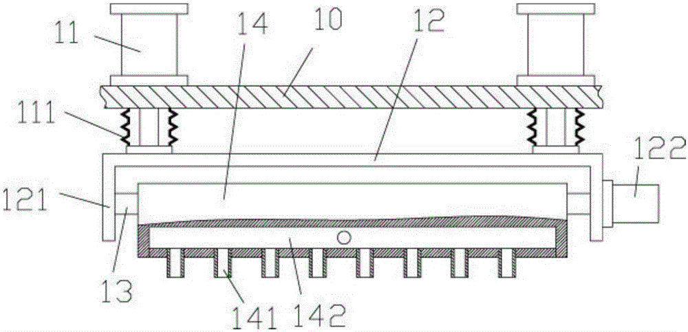
[0028] Examples, see e.g. Figure 1 to Figure 3 As shown, a laser drilling waste collection mechanism includes a laser drilling frame 100, the upper part of the laser drilling frame 100 is a processing box 10, and at least two telescopic cylinders are fixed on the top plate of the processing box 10 11. The push rod of the telescopic cylinder 11 passes vertically downward through the top plate of the processing box 10 and is fixed with a rotating connecting frame 12. The rotating rod 13 is under the rotating connecting frame 12, and the two ends of the rotating rod 13 are hinged on the rotating connecting frame. On the vertical plates 121 that both sides of 12 have, on the outer wall of one of the vertical plates 121, a rotation adjustment motor 122 is fixed, and the output shaft of the rotation adjustment motor 122 is a spline shaft, and the spline shaft is sleeved on the rotating rod 13 In the spline hole that one end of the blower has, the blowing box body 14 is fixed on the...


PUM


Abstract

The invention discloses a laser drilling waste collecting mechanism which comprises a laser drilling rack; a processing box body is arranged on the upper part of the laser drilling rack; at least two telescopic air cylinders are fixedly arranged on the top plate of the processing box body; pushing rods of the telescopic air cylinders downwards pass through the top plate of the processing box body vertically, and are fixedly equipped with a rotary connecting frame; a rotary rod is positioned below the rotary connecting frame; the two ends of the rotary rod are hinged on the vertical plates hinged at the two sides of the rotary connecting frame; a rotary regulating motor is fixedly arranged on the outer side wall of one vertical plate; the output shaft of the rotary regulating motor is a spline shaft; the spline shaft is in plug bush in a spline hole in one end of the rotary rod; an air blowing box is fixedly arranged on the rotary rod; and a plurality of gas jetting tubes are connected on the bottom surface of the air blowing box. The laser drilling waste collecting mechanism disclosed by the invention can be used for automatically collecting waste without manual processing, so that cleanliness of a laser equipment operation environment is guaranteed, and operation of the laser drilling waste collecting mechanism is guaranteed to be normal; and moreover, people do not inhale waste, so that influence on health is reduced.

Description

[0001] Technical field: [0002] The invention relates to the technical field of cleaning processing equipment, in particular to a laser drilling waste collection mechanism. [0003] Background technique: [0004] Laser drilling is the earliest practical laser processing technology, and it is also one of the main application fields of laser processing. [0005] Existing laser cutting devices only perform laser cutting when processing parts. During the processing, some waste materials such as smoke, dust and processing residues will be attached to the surface of the lens and the workpiece, which affects the processing quality of the workpiece and pollutes the In severe cases, the lens will be burned and the optical system will be damaged. [0006] Therefore, waste materials such as smoke, dust and processing residues after processing need to be removed in time. The existing waste materials are generally processed manually, which is easy to inhale the waste materials, which affe...

Claims


Application Information

Patent Timeline
Patent Type & Authority Applications(China)
IPC IPC(8): B23K26/382B23K26/16
CPCB23K26/16B23K26/382
Inventor 李风浪李舒歆
Owner 郑招才
Why Eureka
Try Eureka