
A gripping mechanism for circular thin plate processing for new energy vehicles

A new energy vehicle, grabbing mechanism technology, applied in conveyors, conveyor objects, transportation and packaging, etc., can solve problems such as troublesome manual feeding, low efficiency, and unsatisfactory effects.

Active Publication Date: 2018-10-02
ZHEJIANG JINYUAN IND CO LTD
View PDF7 Cites 0 Cited by
  • Summary
  • Abstract
  • Description
  • Claims
  • Application Information

AI Technical Summary

Problems solved by technology

[0002] In the current processing of the automobile vacuum booster shell, the material is usually loaded manually. The circular thin plate to be extruded is taken out of the barrel and then placed in the lower mold for processing. Manual loading is troublesome. Inefficient and not ideal

Method used


Image

  • A gripping mechanism for circular thin plate processing for new energy vehicles
  • A gripping mechanism for circular thin plate processing for new energy vehicles
  • A gripping mechanism for circular thin plate processing for new energy vehicles

Examples


Embodiment Construction

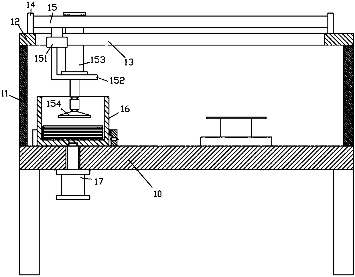
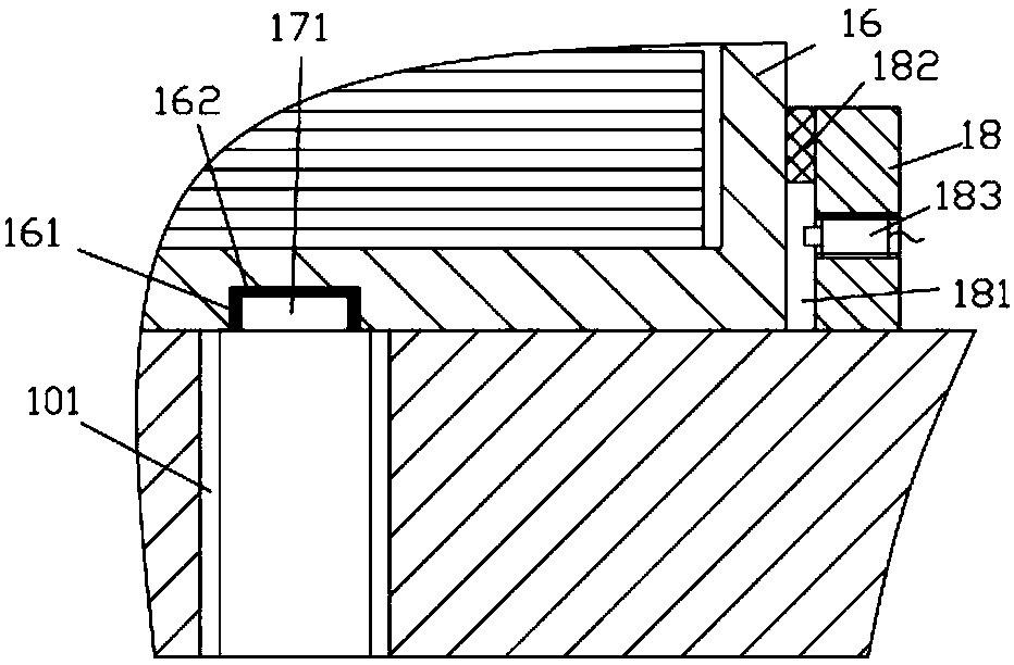
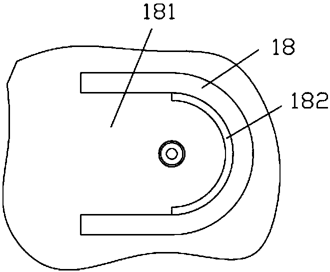
[0017] Example, see as Figure 1 to 3 As shown, a circular sheet processing and grasping mechanism for new energy vehicles includes a frame 10, the left and right sides of the top plate of the frame 10 are fixed with vertical support plates 11, and the upper plate body 12 is fixed on two vertical On the top surface of the straight support plate 11, the middle part of the upper plate body 12 has a moving through groove 13, the left and right ends of the top surface of the upper plate body 12 are fixed with connecting plates 14, and the two ends of the rodless cylinder 15 are fixed in two connecting On the plate 14, a movable connecting block 151 is fixed on the moving block of the rodless cylinder 15, and the movable connecting block 151 is inserted and sleeved in the moving through groove 13. The bottom surface of the movable connecting block 151 is fixed with a connecting frame 152, and the bottom of the connecting frame 152 A telescopic cylinder 153 is fixed. The push rod of ...


PUM


Abstract

The invention discloses a circular thin plate machining and grabbing mechanism used for new energy automobiles. The circular thin plate machining and grabbing mechanism comprises a rack. Two vertical supporting plates are fixed to the left side and the right side of a top plate of the rack; an upper plate body is fixed to the top faces of the two vertical supporting plates; a movable through groove is formed in the middle of the upper plate body; two connecting plates are fixed to the left end and the right end of the top face of the upper plate body; the two ends of a rodless cylinder are fixed to the two connecting plates; a movable connecting block is fixed to a movable block of the rodless cylinder and sleeved with the movable through groove in an inserted mode; a connecting rack is fixed to the bottom face of the movable connecting block; a telescopic cylinder is fixed to a bottom plate of the connecting rack; a push rod of the telescopic cylinder penetrates through the bottom plate of the connecting rack; a vacuum sucker is fixed to the push rod of the telescopic cylinder; a charging basket is paced on the portion, opposite to the vacuum sucker, of the top plate of the rack. According to the circular thin plate machining and grabbing mechanism, a circular thin plate can be automatically grabbed out, manual grabbing is not needed, and convenience is achieved.

Description

Technical field: [0001] The invention relates to the technical field of new energy automobile manufacturing, and more specifically to a circular sheet processing and grasping mechanism for new energy automobiles. Background technique: [0002] In the current processing of automobile vacuum booster shells, the feeding method is generally manual feeding. The circular sheet to be extruded is taken out of the barrel and then placed in the lower mold for processing. The manual feeding is troublesome. The efficiency is low, and the effect is not ideal. Summary of the invention: [0003] The purpose of the present invention is to overcome the shortcomings of the prior art and provide a circular sheet processing and grasping mechanism for new energy vehicles, which can automatically grasp and take out the circular sheet without manual picking, which is very convenient. [0004] The solution of the present invention to solve the technical problem is: [0005] A circular thin plate processing...

Claims


Application Information

Patent Timeline
Patent Type & Authority Patents(China)
IPC IPC(8): B65G47/91
CPCB65G47/912B65G2201/022
Inventor 赵鸿斌
Owner ZHEJIANG JINYUAN IND CO LTD
Learn More