
Biogas pool

A biogas digester and gas chamber technology, applied in the field of biogas application, can solve problems such as poor fermentation effect and non-flowing biogas slurry

Inactive Publication Date: 2017-02-15
CHONGQING XIPU AGRI DEV CO LTD
View PDF0 Cites 0 Cited by
  • Summary
  • Abstract
  • Description
  • Claims
  • Application Information

AI Technical Summary

Problems solved by technology

[0003] The invention provides a biogas digester, which solves the technical problems in the prior art that the biogas slurry in the biogas digester does not flow and the fermentation effect is poor

Method used


Image

  • Biogas pool

Examples


Embodiment Construction

[0009] In order to make the above objects, features and advantages of the present invention more comprehensible, the present invention will be further described in detail below in conjunction with the accompanying drawings and specific embodiments.

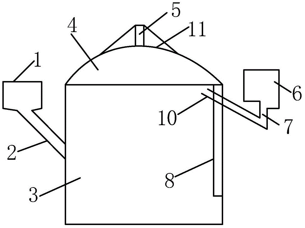
[0010] like figure 1 Shown is a biogas digester, including: feed port 1, feed pipe 2, fermentation tank 3, air chamber 4, movable cover plate 11, and air duct 5. The feed pipe 2 communicates with the fermentation tank 3 and is located on the left side of the fermentation tank. The hydraulic pool 6 is arranged on the right side of the fermentation tank 3, and the bottom of the hydraulic pool 6 is connected with a water seal pool 7, and the bottom surface of the water seal pool 7 has a certain slope. The hydraulic tank 6 communicates with the fermentation tank 3 through a discharge pipe 8 . When producing gas, the pressure of the air chamber 4 pushes the biogas slurry and biogas residue in the pond body into the hydraulic tank 6 t...


PUM


Abstract

The present invention relates to the biogas application field, and discloses a biogas pool, which comprises a material inlet, a material inlet pipe, a fermentation tank, a movable cover, a gas guide pipe and a water pressure tank, wherein the bottom portion of the fermentation tank is connected to a material outlet pipe, the upper end of the material outlet pipe is connected to the water pressure tank, the material outlet pipe is provided with a check valve, a reflux pipe is connected between the fermentation tank and the water pressure tank, the upper end of the reflux pipe is positioned in the upper portion gas chamber inside the fermentation tank, and the lower end is positioned on the bottom portion of the water pressure tank. According to the present invention, the complete fermentation decomposition of the floating water fermentation material is achieved, the crusting is not generated, the gas production effect is not increased, and the crust breaking purpose is achieved through the circulation flow.

Description

technical field [0001] The invention relates to the field of biogas application, in particular to a biogas digester. Background technique [0002] At present, the household hydraulic biogas digester is mainly composed of a feed inlet, a feed pipe, a fermentation tank, a discharge pipe, a movable cover, an air guide pipe, and a hydraulic tank. The feed pipe and the discharge pipe are connected with the fermentation tank. They are respectively located on both sides of the fermentation tank, one end of the discharge pipe is also connected to the hydraulic tank on one side of the fermentation tank, and the air guide tube is located on the movable cover of the fermentation tank. This traditional biogas digester has the following disadvantages: first, the biogas slurry does not flow, the strains are unevenly distributed, and the gas production is low; second, the raw materials are unevenly distributed in the pond, and the fermentation effect is poor; Normal gas production; Fourth...

Claims


Application Information

Patent Timeline
Patent Type & Authority Applications(China)
IPC IPC(8): C12M1/107
CPCC12M21/04C12M27/18Y02E50/30
Inventor 刘先平
Owner CHONGQING XIPU AGRI DEV CO LTD
Learn More