Telescopic drill pipe

A technology of telescopic drill pipes and drill pipes, which is applied in the field of drill pipes and telescopic drill pipes. It can solve the problems that the length of drill pipes cannot be adjusted in real time, and achieve the effects of reducing the time for connecting drill pipes and increasing the drilling speed.

Inactive Publication Date: 2017-02-15
周兆弟
View PDF11 Cites 4 Cited by
  • Summary
  • Abstract
  • Description
  • Claims
  • Application Information

AI Technical Summary

Problems solved by technology

However, the shortcoming of this scheme is that the le

Method used


Image

  • Telescopic drill pipe
  • Telescopic drill pipe
  • Telescopic drill pipe

Examples


Embodiment 1

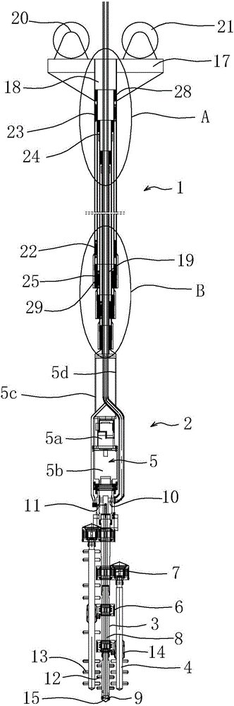
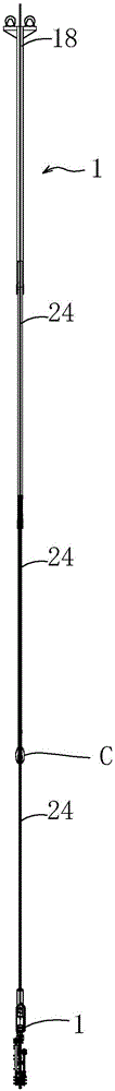
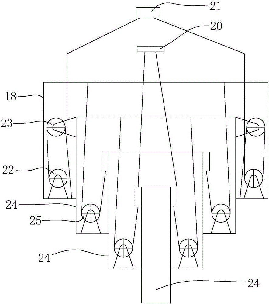
[0035] like figure 1 As shown, a telescopic drill rod includes a drill rod mechanism 1 and a drill bit mechanism 2 fixed at the end of the drill rod mechanism 1. The drill rod mechanism 1 can reciprocate along the axial direction so as to change the length of the drill rod mechanism 1 The drill bit mechanism 2 includes a main drill rod 3 capable of rotating in the circumferential direction and several auxiliary drill rods 4 arranged around the main drill rod 3, at least one auxiliary drill rod 4 rotates in the same direction as the main drill rod 3 and at least The direction of rotation of an auxiliary drill rod 4 is opposite to that of the main drill rod 3 . The auxiliary drill rod 4 and the main drill rod 3 can be distributed in the structure shown in FIG. 12 .

[0036] In this embodiment, an oil cylinder can be installed at the end of the drill rod mechanism 1, and the output end of the oil cylinder is connected to the drill bit mechanism 2. When the oil cylinder works, th...

Embodiment 2

[0051] The structure and working principle of this embodiment are basically the same as that of Embodiment 1, the difference is that, as figure 1 As shown, the air delivery pipe 26 and the material delivery pipe 27 penetrate into the innermost movable drill pipe 24 from the installation platform 17, and penetrate into the main drill pipe 3 all the time, and pass through the main drill from above the main drill pipe rotary driver 5 The rod 3 is connected with the air inlet 11 and the concrete feed port 10 , and the air inlet 11 and the concrete feed port 10 are connected with the conveying channel 8 .

[0052] to combine Image 6 Shown, except the movable drill rod 24 that connects main drill rod 3, all the other movable drill rods 24 bottom inner walls are provided with a movable drill rod guiding mud scraping sleeve 24a, and the structure of movable drilling rod guiding mud scraping sleeve 24a can be compared with The structure of the guide mud scraping sleeve 29 of the mova...


PUM


Abstract

The invention belongs to the technical field of buildings, and relates to a telescopic drill pipe. The telescopic drill pipe comprises a drill pipe mechanism and a drill bit mechanism fixedly arranged on the end part of the drill pipe mechanism, wherein the drill pipe mechanism can move back and forth in the axial direction to change length of the drill pipe mechanism; the drill bit mechanism comprises a primary drill pipe which can rotate in the circumferential direction and a plurality of secondary drill pipes which are arranged around the primary drill pipe; and the rotation direction of at least one secondary drill pipe is the same with that of the primary drill pipe, and the rotation direction of at least one secondary drill pipe is reverse to that of the primary drill pipe. The drill pipe mechanism and the drill bit mechanism are combined to form the telescopic drill pipe, so that the telescopic drill pipe can automatically drill downwards without external force, and therefore, time of connecting drill pipes is reduced; and the telescopic drill pipe is very convenient and quick, is high in drilling speed, can drill to target depth and is returned to the middle without stop, so that guniting hole blockage is not caused by stop.

Description

technical field [0001] The invention belongs to the technical field of construction and relates to a drill pipe, in particular to a telescopic drill pipe used for making a mixing pile. Background technique [0002] At present, there are two types of piling machines used on construction sites: one is the rotary piling machine. The structure of this piling machine is a drill pipe suspension frame pulled up by a hoist, and the drill pipe bit is driven by the power head to form a hole in the underground drilling machine. The other is the impact hammer pile driver. The structure of this pile driver is to use the hoist to pull up the impact hammer and drop it repeatedly, and then lift it to realize pile driving. Among them, the rotary pile driver mainly realizes the purpose of drilling the drill pipe underground through the circumferential rotation of the drill pipe during piling. When the drill pipe is drilled, grouting is used to cool the drill pipe and perform grouting operatio...

Claims


Application Information

Patent Timeline
IPC IPC(8): E21B7/00E21B17/00E21B19/084E21B21/14E21B4/02
CPCE21B7/002E21B4/02E21B17/00E21B17/006E21B19/084E21B21/14
Inventor 周兆弟
Owner 周兆弟
Why Eureka
Try Eureka