Air cylinder, slip sheet spring fixing structure and rotary compressor
A compressor and cylinder technology, applied in the field of compressors, can solve problems such as high cost and complex spring fixing structure, achieve low production cost, improve operation efficiency and performance COP, and reduce the effect of contact area
- Summary
- Abstract
- Description
- Claims
- Application Information
AI Technical Summary
Problems solved by technology
Method used
Image


Examples
Embodiment 1
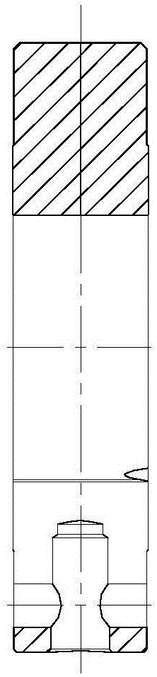
[0042] Such as Figure 4 As shown, this embodiment provides a compressor cylinder 1, which is especially suitable for rotary compressors. The cylinder 1 is provided with a slide groove 11 radially on the wall of the cylinder 1, and a spring hole 12 communicating with the slide groove 11 is arranged on the radially outer side of the slide groove 11. The tail of the spring hole 12 is The end is the closed end 121 formed by the wall of the cylinder 1; the spring hole 12 is provided with a spring installation guide port 13 communicating with the spring hole 12 on at least one side of the cylinder 1 wall on both sides of the cylinder 1 axial direction. .
[0043] By setting the tail end of the spring hole 12 as the closed end 121 formed by the wall of the cylinder 1, it prevents the sliding plate spring 3 from being pushed out of the spring hole 12 by the sliding plate 2 during work, which is beneficial to ensure the reliability of the compressor. At the same time, the noise insi...
Embodiment 2
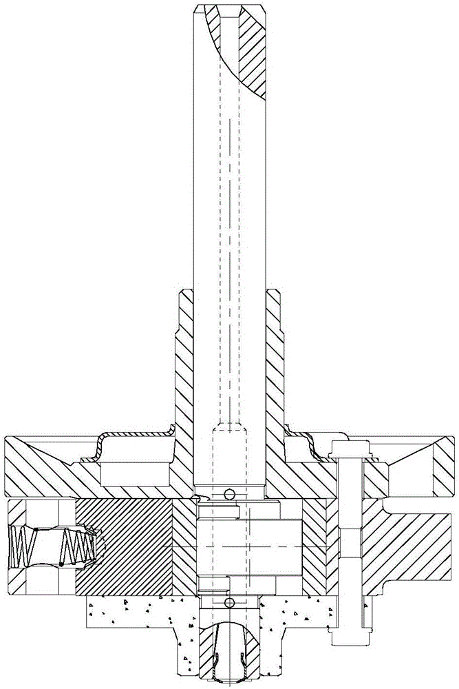
[0048] This embodiment provides a fixing structure for the sliding leaf spring 3 , including the cylinder 1 , the sliding leaf 2 and the sliding leaf spring 3 in the first embodiment. Wherein, the slider 2 is reciprocally slidably arranged in the slider groove 11 of the cylinder 1, the slider spring 3 is arranged in the spring hole 12 of the cylinder 1, one end is connected to the tail of the slider 2, and the other end is connected to the tail of the slider 2. One end abuts against the closed end 121 of the spring hole 12 .
Embodiment 3
[0050] This embodiment provides a rotary compressor, including a closed casing, a motor assembly and a compression pump body arranged in the closed casing, a gas-liquid separator communicated with the compression pump body in the compressor through an intake pipe, and a gas-liquid separator in the closed casing The upper end is provided with an exhaust pipe. The motor assembly of the compressor includes a stator and a rotor, and the compressor shaft is driven to rotate by the rotor. The compression pump body includes an upper flange 5, a cylinder 1 and a lower flange 6 which are sequentially installed along the axial direction of the compressor shaft. The cylinder 1 in this embodiment is the cylinder 1 in the first embodiment. The cylinder 1 is equipped with a roller installed on the eccentric part of the compressor shaft. When the compressor shaft rotates, the roller is driven to roll along the inner wall of the cylinder 1. The intake pipe communicates with the inner cavity ...
PUM
 Abstract
Description
Claims
Application Information
 - R&D
- Intellectual Property
- Life Sciences
- Materials
- Tech Scout
- Unparalleled Data Quality
- Higher Quality Content
- 60% Fewer Hallucinations
Browse by: Latest US Patents, China's latest patents, Technical Efficacy Thesaurus, Application Domain, Technology Topic, Popular Technical Reports.
© 2025 PatSnap. All rights reserved.Legal|Privacy policy|Modern Slavery Act Transparency Statement|Sitemap|About US| Contact US: help@patsnap.com