Pressure following sealing liquid isolation system used for mechanical sealing

A mechanical seal and isolation system technology, applied in the direction of fluid pressure actuating devices, etc., can solve problems such as insufficient pressure following performance, worn cylinders, piston jamming failure, etc., to improve pressure following performance and sealing performance, prevent failure, The effect of reducing the probability of system seal failure

Inactive Publication Date: 2017-02-15
FLOWSERVE FLUID MOTION & CONTROL SUZHOU
View PDF7 Cites 2 Cited by
  • Summary
  • Abstract
  • Description
  • Claims
  • Application Information

AI Technical Summary

Problems solved by technology

However, the pressure following performance of the existing corresponding products is insufficient

Method used


Image

  • Pressure following sealing liquid isolation system used for mechanical sealing
  • Pressure following sealing liquid isolation system used for mechanical sealing

Examples


Example Embodiment

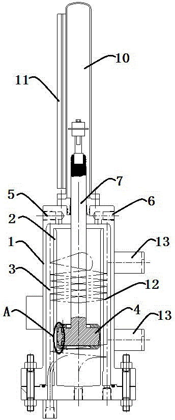
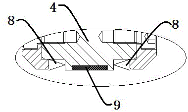
[0017] Example: refer to figure 1 , 2 As shown, a pressure-following sealing liquid isolation system for mechanical seals includes an outer cylinder 1 (the outer cylinder 1 is a hollow structure with both ends sealed), an inner cylinder 2 placed inside the outer cylinder 1, The interlayer cavity 3 between the outer cylinder 1 and the inner cylinder 2, the piston 4 inside the inner cylinder 2, and the liquid outlet 5 and the liquid inlet 6 arranged on the outer cylinder 1; the piston 4 will The inner cylinder body 2 is divided into an upper chamber and a lower chamber, and the lower chamber is connected with the medium side pressure pipe, the upper chamber is connected with the interlayer chamber 3 and has a built-in spacer liquid, and the liquid outlet 5 and the liquid inlet 6 are connected with the upper chamber. The cavity is connected, the upper end surface of the piston 4 is provided with a piston rod 7, the piston rod 7 is sealingly connected with the top surface of the ...


PUM


Abstract

The invention discloses a pressure following sealing liquid isolation system used for mechanical sealing. The system comprises an outer cylinder body, an inner cylinder body located in the outer cylinder body, an interlayer cavity located between the outer cylinder body and the inner cylinder body, a piston arranged in the inner cylinder body, a liquid outlet and a liquid inlet, wherein the liquid outlet and the liquid inlet are formed in the outer cylinder body; the inner cylinder body is separated into an upper cavity and a lower cavity through the piston, the lower cavity is communicated with a medium side pressure drawing pipe, the upper cavity is communicated with the interlayer cavity and internally contains isolation liquid, the liquid outlet and the liquid inlet are communicated with the upper cavity, a piston rod is arranged on the upper end face of the piston, the piston rod is in seal connection with the top face of the outer cylinder body and extends out of the outer cylinder body, and meanwhile the two ends of the piston are each sleeved with a V-shaped spring sealing ring. A wear-resisting ring is arranged at the position, between the two V-shaped spring sealing rings, of the piston. The pressure following sealing liquid isolation system has the beneficial effects that the pressure difference between the hydraulic force and the medium side is constantly isolated, real-time following under different pressures is achieved, the piston is effectively prevented from being clamped and failing, and meanwhile the risk that the piston wears the cylinder bodies is reduced.

Description

technical field [0001] The invention belongs to a mechanical seal auxiliary system, in particular to a pressure-following seal liquid isolation system for a mechanical seal. Background technique [0002] Mechanical seal (mechanical seal) refers to at least one pair of end faces perpendicular to the axis of rotation, under the action of fluid pressure and the elastic force (or magnetic force) of the compensation mechanism, and the cooperation of the auxiliary seal to keep fit and slide relative to prevent fluid leakage. device. A mechanical seal is an oil seal device for rotating machinery, such as centrifugal pumps, centrifuges, stirring tanks, and compressors. [0003] In actual use, in pumps and similar rotating equipment, due to the high speed of the double-end mechanical seal used in the pump, an axial spiral pumping ring is generally placed on the mechanical seal rotor in the industry to generate a small lift and drive the seal. The liquid circulation flow overcomes t...

Claims


Application Information

Patent Timeline
IPC IPC(8): F15B15/14F15B15/20
CPCF15B15/1452F15B15/1428F15B15/20
Inventor 韩若光严慧君
Owner FLOWSERVE FLUID MOTION & CONTROL SUZHOU
Why Eureka
Try Eureka