Gear shifting wire drawing joint assembly and wire drawing assembly

A technology for gear-drawing and assembly, which is applied in the field of gear-shifting wire-drawing joint assembly and wire-drawing assembly, which can solve the problems of increased friction between wire 3 and sheath 4 and reduced shifting efficiency, so as to reduce friction and improve The effect of shift efficiency

Inactive Publication Date: 2017-02-15
ANHUI JIANGHUAI AUTOMOBILE GRP CORP LTD
View PDF4 Cites 5 Cited by
  • Summary
  • Abstract
  • Description
  • Claims
  • Application Information

AI Technical Summary

Problems solved by technology

However, when the wire drawing joint 2 is driven by the ball head to move along the Y-axis direction, since one end of the wire drawing 3 is fixedly connected with the shift bracket on the transmission through the sheath 4, the wire drawing 3 will be offset relative to the axis of the sheath 4 in the Y-axis direction. Shifting at a certain angle will increase the friction between the wire drawing 3 and the sheath 4, thereby reducing the shifting efficiency

Method used


Image

  • Gear shifting wire drawing joint assembly and wire drawing assembly
  • Gear shifting wire drawing joint assembly and wire drawing assembly
  • Gear shifting wire drawing joint assembly and wire drawing assembly

Examples


Embodiment Construction

[0029] Embodiments of the present invention are described in detail below, examples of which are shown in the drawings, wherein the same or similar reference numerals designate the same or similar elements or elements having the same or similar functions throughout. The embodiments described below by referring to the figures are exemplary only for explaining the present invention and should not be construed as limiting the present invention.

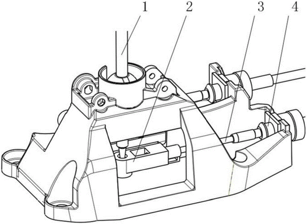
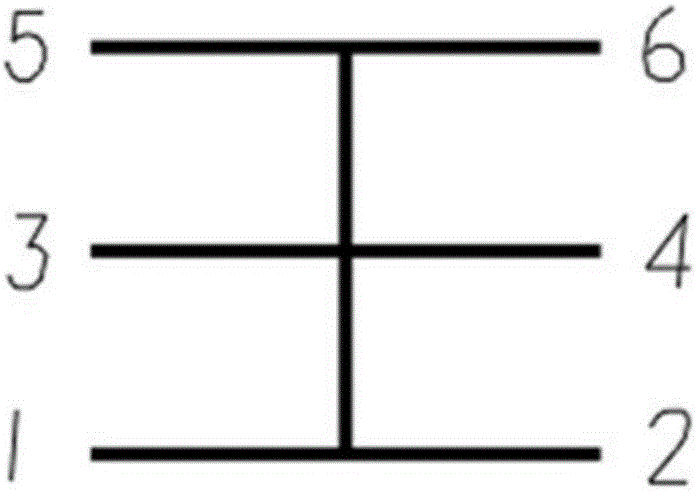
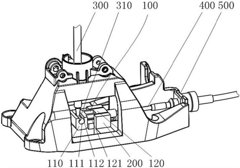
[0030] figure 2 It is a schematic diagram of the car gear, image 3 The state diagram of the shift drawing joint assembly provided in the embodiment of the present invention in practical application, Figure 4 Schematic diagram of the structure of the shift wire joint assembly provided by the embodiment of the present invention.

[0031] Please also refer to Figure 2 to Figure 4 , the embodiment of the present invention provides a shift wire joint assembly, including a wire joint 100 and a guide rail 200, wherein the wire joint 100 ...


PUM


Abstract

The invention discloses a gear shifting wire drawing joint assembly and a wire drawing assembly. The gear shifting wire drawing joint assembly comprises a wire drawing joint and guide rails; the wire drawing joint comprises a control part and a guide part; a sliding groove is formed in the control part, and is matched with a ball head on the gear shifting rod; the guide rails abut against the two side faces of the guide part; according to the gear shifting wire drawing joint assembly and the wire drawing assembly, through the sliding groove and the guide rails, in the gear selecting and shifting process, a drawn wire can move in the axial direction, friction force between the drawn wire and a protection sleeve is reduced, and the gear shifting efficiency is improved.

Description

technical field [0001] The invention relates to the technical field of automobiles, in particular to a shift wire drawing joint assembly and a wire drawing assembly. Background technique [0002] In manual transmission cars, wires are usually used to control the gear position. Generally, the shift handle is connected to one end of the shift wire, and the other end of the shift wire is connected to the shift bracket on the transmission. By operating the shift The handle is used to pull or push the shift wire, and the shift force is transmitted to the shift bracket through the shift wire, and then transmitted to the internal shift mechanism of the transmission to realize the shift function. [0003] figure 1 It is a schematic diagram of the cooperation between the drawing joint and the shift lever in the prior art, figure 2 Schematic diagram of car gears. [0004] Please also refer to figure 1 and figure 2 , in the prior art, the end of the shift lever 1 is provided wit...

Claims


Application Information

Patent Timeline
Patent Type & Authority Applications(China)
IPC IPC(8): F16H59/02F16C1/14
CPCF16H59/0278F16C1/14
Inventor 黄从奎陈健章昊燕逸飞杨允辉陆静静岳丽姣
Owner ANHUI JIANGHUAI AUTOMOBILE GRP CORP LTD
Why Eureka
Try Eureka