High-temperature mechanical sealing structure

A mechanical seal and high-temperature technology, which is applied to engine seals, mechanical equipment, engine components, etc., can solve the problems of difficult surface processing of ceramic materials, rising temperature of static ring and dynamic ring, and replacement of metal materials, etc., so as to improve the service life , reduce friction, good mechanical sealing performance

Inactive Publication Date: 2017-02-15
ZHEJIANG UNIV
View PDF5 Cites 10 Cited by
  • Summary
  • Abstract
  • Description
  • Claims
  • Application Information

AI Technical Summary

Problems solved by technology

[0004] In order to solve the problems in the background technology that dry friction under high temperature causes the temperature rise of the static ring and the moving ring to be too high, and the wear is aggravated, the problem of difficult surface processing of ceramic materials, and the problem of frequent replacement of metal materials

Method used


Image

  • High-temperature mechanical sealing structure

Examples


Embodiment Construction

[0016] The present invention will be further described below in conjunction with the accompanying drawings and embodiments.

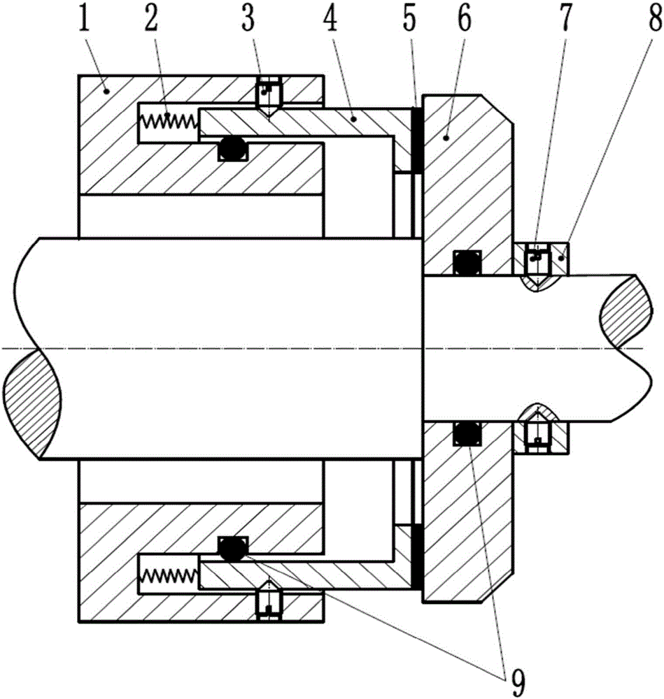
[0017] Such as figure 1 As shown, the static ring 4 of the present invention is coated with a layer of alloy coating 5, and the entire static ring is installed on the shaft, and the axis of the static ring is kept coincident with the axis of the shaft during installation. There are first set screws 3 on both sides of the outer symmetrical side of the sleeve 1, and the first set screws 3 pass through the sleeve 1 and connect to the outside of the static ring 4 and fix the static ring 4 in the axial direction to limit the rotation of the static ring 4, but The static ring 4 is allowed to move slightly along the axial direction. The end surface of the static ring 4 installed in the annular groove is connected to the bottom surface of the annular groove through the spring 2, and through the extrusion of the spring 2, the end surface of the static ring 4 ou...


PUM


Abstract

The invention discloses a high-temperature sealing structure. The big end of a shaft is sleeved with a sleeve tube, and an annular groove is formed in the end face of the sleeve tube. One end of a static ring is mounted into the annular groove in an inserted mode and is in sealing connection with the inner wall of the annular groove through an O-shaped rubber ring. First fastening screws are arranged on the two symmetric sides of the outer side of the sleeve tube, and the first fastening screws penetrate through the sleeve tube to be connected to the outer side of the static ring, so that the static ring is fixedly in the axial direction and is restrained from rotating. The end face, mounted in the annular groove, of the static ring is connected with the bottom face of the annular groove through a spring, and the end face, located outside the annular groove, of the static ring is connected with a movable ring through a special ally coating. The small end of the shaft is sleeved with the movable ring, and the movable ring is positioned through a shaft shoulder and then is fixed axially through a locking baffle ring and a second fastening screw. According to the high-temperature sealing structure, the friction condition between the movable ring and the static ring under the high-temperature state is changed to fluid friction from high friction, friction, abrasion and dielectric leakage between the movable ring and the static ring are reduced, the service life of the movable ring and the static ring is prolonged, and the good mechanical sealing performance between the end face of the movable ring and the end face of the static ring is guaranteed.

Description

technical field [0001] The invention relates to a sealing structure, in particular to a high-temperature mechanical sealing structure. Background technique [0002] Mechanical seal refers to at least one pair of end faces perpendicular to the axis of rotation, under the action of fluid pressure and the elastic force (or magnetic force) of the compensation mechanism and the cooperation of the auxiliary seal, it is kept in place and relatively sliding to prevent fluid leaking device. [0003] In the existing mechanical seal device, the sealing end surface is usually formed by direct contact between the stationary ring and the moving ring. This direct contact method makes the lubricating oil film between the static ring and the moving ring very thin (usually only a few microns thick), so dry friction is easily formed between the moving ring and the static ring, and it is easy to cause friction between the moving ring and the static ring. wear and tear. As the friction time b...

Claims


Application Information

Patent Timeline
Patent Type & Authority Applications(China)
IPC IPC(8): F16J15/34
CPCF16J15/3496
Inventor 彭鹏冯彦午汪久根
Owner ZHEJIANG UNIV
Why Eureka
Try Eureka