
Blade tip clearance real-time measurement system and method based on constant voltage alternating current discharge

A technology for real-time measurement of blade tip clearance, applied to measurement devices, electrical devices, electromagnetic means, etc., can solve the problems of friction between the blade tip and the inner wall of the casing, affecting the safety of the engine, and damage to parts, and achieves a novel measurement method. , Improve system stability and strong practicability

Active Publication Date: 2017-02-15
南京科唯信智慧科技有限公司
View PDF10 Cites 10 Cited by
  • Summary
  • Abstract
  • Description
  • Claims
  • Application Information

AI Technical Summary

Problems solved by technology

However, if the blade tip clearance is too small, due to the expansion of the blade due to heating in a high temperature environment, it may cause friction between the blade tip and the inner wall of the casing, resulting in damage to parts and affecting the safety of the engine

Method used


Image

  • Blade tip clearance real-time measurement system and method based on constant voltage alternating current discharge
  • Blade tip clearance real-time measurement system and method based on constant voltage alternating current discharge
  • Blade tip clearance real-time measurement system and method based on constant voltage alternating current discharge

Examples


Embodiment Construction

[0023] The technical solutions of the present invention will be described in detail below in conjunction with the accompanying drawings.

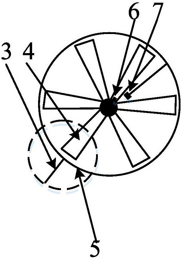
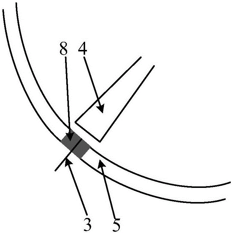
[0024] Such as Figure 4 As shown, the present invention provides a real-time measurement system for blade tip clearance based on constant-voltage AC discharge, including a high-frequency AC discharge voltage source 1, a negative feedback discharge coupling circuit module 2, a metal probe 3, a magnet 6, a Hall The sensor 7, the detection resistor 9, the voltage sensor 10, the analog-to-digital converter 11, the signal acquisition and conversion circuit 12 and the data processing module 13 will be introduced separately below.

[0025] A negative feedback discharge coupling circuit module 2 is connected in series between the high voltage end of the high frequency AC discharge voltage source 1 and the metal probe 3, and the cathode of the high frequency AC discharge voltage source 1 is connected to another negative feedback discharge coupling ...


PUM


Abstract

The invention provides a blade tip clearance real-time measurement system and method based on constant voltage alternating current discharge. The system comprises a high-frequency alternating current discharge voltage source, a negative feedback discharge coupling circuit module, a metal probe, a magnet, a Hall sensor, a current magnitude measurement conversion module, a signal acquisition conversion circuit and a data processing module. A circuit module is connected in series between the voltage source high voltage end and the metal probe. The voltage source cathode is connected with the rotor blade center sequentially through the current magnitude measurement conversion module and another circuit module. One end of the metal probe is flush with the inner wall of a casing, and the other end is exposed to the outside. The current magnitude measurement conversion module is connected with the data processing module. The magnet is located at the off center of a rotation shaft. The Hall sensor is fixed on one side of the rotation shaft. The Hall sensor is connected with the data processing module through the signal acquisition conversion circuit. The data processing module is connected with the voltage source control end. The actual blade tip clearance of each blade can be measured in the measurement range. The system has the advantages of high practicality and easy installation and use.

Description

technical field [0001] The invention belongs to the field of blade clearance measurement, in particular to a real-time measurement system and method of blade tip clearance based on constant-voltage AC discharge, which can measure the actual blade tip clearance of each blade within the measurement range. Background technique [0002] The tip clearance of an aeroengine blade generally refers to the radial clearance between the engine rotor blade and the casing. Tip clearance is a basic measurement parameter in the engine development process, and at the same time, it is also an important part of active tip clearance control, health management and fault diagnosis of the engine during operation. [0003] As an important parameter of a gas turbine engine, the size of the tip clearance of the turbine and compressor blades has a great influence on the efficiency of the engine. When the radial clearance between the engine rotor tip and the inner wall of the casing is too large, the c...

Claims


Application Information

Patent Timeline
Patent Type & Authority Applications(China)
IPC IPC(8): G01B7/15
CPCG01B7/15
Inventor 于兵申恩玉胡忠志王继强袁培舒文君
Owner 南京科唯信智慧科技有限公司
Learn More