
Intelligent impact mapping method detection system

A detection system and impact imaging technology, which is applied in measuring devices, analyzing solids using sound waves/ultrasonic waves/infrasonic waves, and material analysis using sound waves/ultrasonic waves/infrasonic waves. High-level problems, to achieve the effect of fast and efficient collection

Inactive Publication Date: 2017-02-15
深圳领智创科技有限公司
View PDF8 Cites 1 Cited by
  • Summary
  • Abstract
  • Description
  • Claims
  • Application Information

AI Technical Summary

Problems solved by technology

[0005] At present, the equipment system used by the impact image method is relatively simple, the data collection is easily disturbed by the external environment, and the collection quality is not high enough

Method used


Image

  • Intelligent impact mapping method detection system
  • Intelligent impact mapping method detection system

Examples


Embodiment Construction

[0025] Embodiments of the technical solutions of the present invention will be described in detail below in conjunction with the accompanying drawings. The following examples are only used to illustrate the technical solution of the present invention more clearly, so they are only examples, and should not be used to limit the protection scope of the present invention.

[0026] It should be noted that, unless otherwise specified, the technical terms or scientific terms used in this application shall have the usual meanings understood by those skilled in the art to which the present invention belongs.

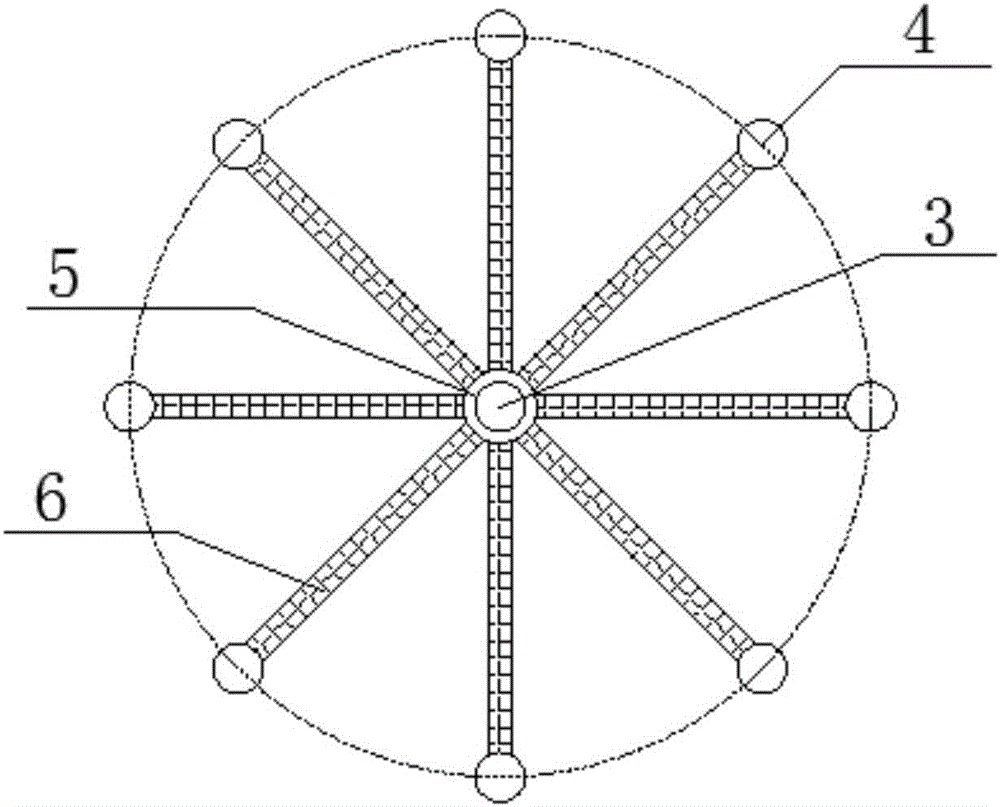
[0027] figure 1 It is a structural schematic diagram of the intelligent impact imaging method detection system provided by the embodiment of the present invention. see figure 1 , the intelligent impact imaging detection system includes:

[0028] A control unit 1, through which the user writes program codes;

[0029] The host unit 2 is connected to the control unit 1, and conv...


PUM


Abstract

The invention relates to the technical field of civil engineering detection, and provides an intelligent impact mapping method detection system. The intelligent impact mapping method detection system comprises a control unit, a host unit, an excitation unit and a receiving unit, wherein a user compiles program code through the control unit; the host unit is connected with the control unit and converts the program code in the control unit into an excitation instruction; the excitation unit is used for responding to the excitation instruction of the host unit, and executing the excitation action; the receiving unit is used for receiving excitation data of the excitation action and sending the excitation data to the host unit. The intelligent impact mapping method detection system provided by the invention has the advantages that the program code of the excitation instruction is compiled through the control unit; the excitation instruction is sent through the host unit; the excitation unit responses the excitation instruction; the receiving unit receives the excitation data of the excitation instruction and sends the excitation data to the host unit; the intelligent control is realized in the whole detection process. The intelligent impact mapping method detection system can fast and efficiently collect the detection data and process the data in real time.

Description

technical field [0001] The invention relates to the technical field of civil engineering non-destructive testing, in particular to an intelligent impact imaging detection system. Background technique [0002] my country's infrastructure construction has made great progress, and major water conservancy facilities, geotechnical and underground projects have been completed one after another, such as aqueducts, bridges, and tunnels. Based on considerable technological progress and expanding market demand, the scale of engineering structures is getting larger and larger. Large-scale engineering structures often adopt concrete structures or prestressed concrete structures. The structure design is complex, the construction technology requirements are high, the quality control is difficult, and engineering quality problems are becoming more and more common. In the stage of concrete construction, the volume of the structure is large, the amount of concrete is large, the pouring spee...

Claims


Application Information

Patent Timeline
IPC IPC(8): G01N29/04
CPCG01N29/045G01N2291/023G01N2291/103
Inventor 冯少孔陈峰彭冬徐超张主超
Owner 深圳领智创科技有限公司
Learn More