Radio frequency power detection circuit
A technology of radio frequency power and detection circuit, which is applied in the direction of measuring electric power, measuring electric variables, electric vehicles, etc., can solve the problem of output voltage swing limitation, and achieve the effect of large output voltage swing
- Summary
- Abstract
- Description
- Claims
- Application Information
AI Technical Summary
Problems solved by technology
Method used
Image

Examples
Embodiment Construction
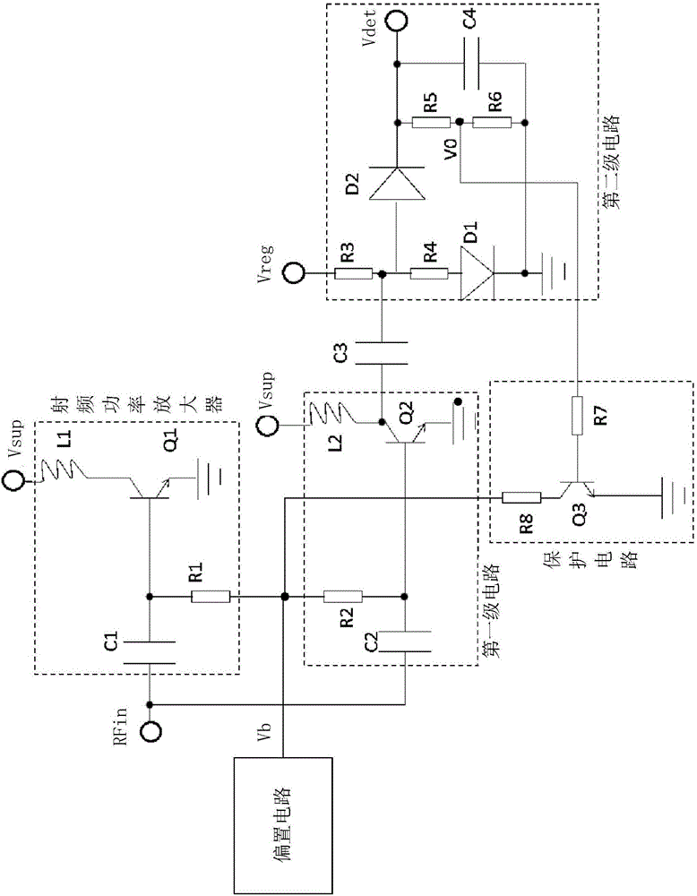
[0027] see figure 2 , which is the RF power detection circuit provided by this application. For ease of description, figure 2 Also included are bias circuits and RF power amplifiers. The bias circuit provides a bias voltage Vb for the power transistor Q1 in the radio frequency power amplifier and the amplifying transistor Q2 in the first stage circuit. The RF power amplifier mainly includes a power transistor Q1 to realize the amplification function. The bias voltage Vb is connected to the base of the power transistor Q1 through a resistor R1 to provide a bias voltage therefor. The radio frequency input signal RFin is connected to the base of the power transistor Q1 through a capacitor C1, and the capacitor C1 is used for DC blocking and RF signal input of the detection circuit. The power supply voltage Vsup is connected to the collector of the power transistor Q1 through the inductor-L1, and the inductor-L1 is used to prevent the RF signal output by the power transistor...
PUM
 Abstract
Description
Claims
Application Information
 - R&D
- Intellectual Property
- Life Sciences
- Materials
- Tech Scout
- Unparalleled Data Quality
- Higher Quality Content
- 60% Fewer Hallucinations
Browse by: Latest US Patents, China's latest patents, Technical Efficacy Thesaurus, Application Domain, Technology Topic, Popular Technical Reports.
© 2025 PatSnap. All rights reserved.Legal|Privacy policy|Modern Slavery Act Transparency Statement|Sitemap|About US| Contact US: help@patsnap.com