Measurement method of reflection coefficient of calibration signal source in microwave power meter

A microwave power meter and reflection coefficient technology, which is used in measurement devices, measurement of electrical variables, instruments, etc., can solve the problems of redundant measurement, complicated measurement process of measurement devices, and inability to give mathematical expressions, and achieve accurate uncertainty. The effect of the assessment

Active Publication Date: 2019-01-22
NAT INST OF METROLOGY CHINA
View PDF10 Cites 0 Cited by
  • Summary
  • Abstract
  • Description
  • Claims
  • Application Information

AI Technical Summary

Problems solved by technology

[0009] 1. This method cannot give a clear mathematical expression of the measured value, and the uncertainty of the measurement result is not easy to evaluate;
[0010] 2. The measuring device and measuring process are complicated;
[0011] 3. Calculation results depend on power measurement accuracy, usually redundant measurements are necessary

Method used

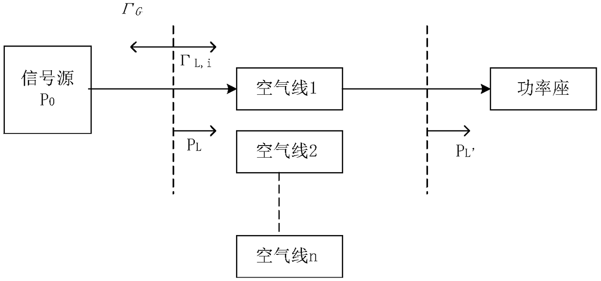

Image

  • Measurement method of reflection coefficient of calibration signal source in microwave power meter
  • Measurement method of reflection coefficient of calibration signal source in microwave power meter
  • Measurement method of reflection coefficient of calibration signal source in microwave power meter

Examples


Embodiment Construction

[0037] Embodiments of the present invention are described in detail below, examples of which are shown in the drawings, wherein the same or similar reference numerals designate the same or similar elements or elements having the same or similar functions throughout. The embodiments described below by referring to the figures are exemplary only for explaining the present invention and should not be construed as limiting the present invention.

[0038] In describing the present invention, it should be understood that the terms "center", "longitudinal", "transverse", "upper", "lower", "front", "rear", "left", "right", " The orientations or positional relationships indicated by "vertical", "horizontal", "top", "bottom", "inner" and "outer" are based on the orientations or positional relationships shown in the drawings, and are only for the convenience of describing the present invention and Simplified descriptions, rather than indicating or implying that the device or element refe...


PUM


Abstract

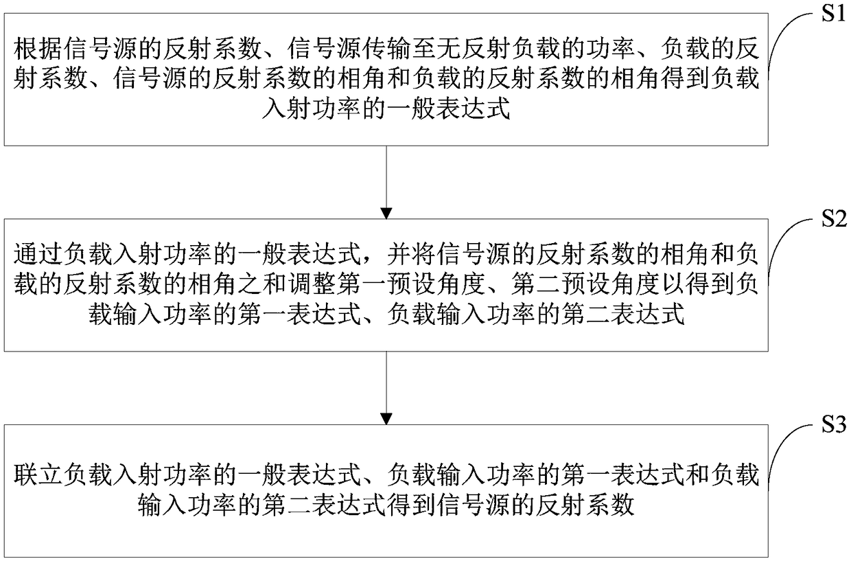
The invention discloses a measurement method of the reflection coefficient of a calibration signal source in a microwave power meter. The method includes the following steps that: the general expression of the incident power of a load is obtained according to the reflection coefficient of the signal source, the power of the transmission of the signal source to the non-reflection load, the reflection coefficient of the load, the phase angle of the reflection coefficient of the signal source and the phase angle of the reflection coefficient of the load; the sum of the phase angle of the reflection coefficient of the signal source and the phase angle of the reflection coefficient of the load is adjusted by a first preset angle and a second preset angle according to the general expression of the incident power of the load, so that the first expression of the incident power of the load, and the second expression of the incident power of the load can be obtained; and the general expression of the incident power of the load, the first expression of the incident power of the load and the second expression of the incident power of the load are associated, so that the reflection coefficient of the signal source can be obtained. According to the measurement method of the invention, the reflection coefficient of the calibration source can be determined through measuring the power quantity value of the calibration source under a specific phase shift condition.

Description

technical field [0001] The invention relates to the field of microwave power meter measurement and specifically designs a method for measuring the reflection coefficient of a calibration signal source in a microwave power meter. Background technique [0002] In order to ensure the measurement accuracy of the microwave power meter, the power meter is usually equipped with a 50MHz, 0dBm calibration signal source (or "reference signal source" hereinafter referred to as "calibration source" or "source") for self-calibration. The existence of mismatch error affects the calibration results, and to evaluate this effect, it is necessary to accurately measure the reflection coefficient of the calibration source. [0003] There is currently no device dedicated to measuring the reflection coefficient of a 50MHz calibration source, but there are some general signal source reflection coefficient measurement methods that can be used to achieve this measurement. [0004] If the reflection...

Claims


Application Information

Patent Timeline
Patent Type & Authority Patents(China)
IPC IPC(8): G01R35/00
CPCG01R35/005
Inventor 崔孝海梁伟军赵巍李勇贾超袁文泽
Owner NAT INST OF METROLOGY CHINA
Why Eureka
Try Eureka