Planar array projection device and depth camera

A projection device and area array technology, applied in the optical field, can solve the problems of large volume and difficult to integrate, and achieve the effect of improving lightness and thinning and good optical projection effect.

Active Publication Date: 2017-02-15
SHENZHEN ORBBEC CO LTD
View PDF5 Cites 71 Cited by
  • Summary
  • Abstract
  • Description
  • Claims
  • Application Information

AI Technical Summary

Problems solved by technology

Among them, an infrared projector is generally composed of a light source, a lens, and a diffractive optical element, and is used to project an infrared image of a certain pattern to the target space, and the light source in the prior art is generally a single laser light source, which is large in size and difficult to Integrate into smaller projectors

Method used


Image

  • Planar array projection device and depth camera
  • Planar array projection device and depth camera
  • Planar array projection device and depth camera

Examples


Embodiment Construction

[0022] The following will clearly and completely describe the technical solutions in the embodiments of the present invention with reference to the accompanying drawings in the embodiments of the present invention. Obviously, the described embodiments are only some, not all, embodiments of the present invention. Based on the embodiments of the present invention, all other embodiments obtained by persons of ordinary skill in the art without making creative efforts belong to the protection scope of the present invention.

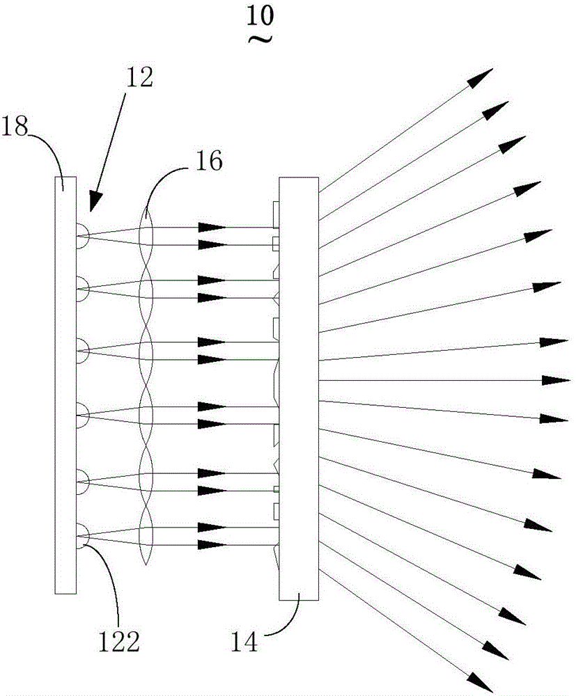
[0023] see figure 1 , figure 1 It is a structural schematic diagram of an embodiment of the area array projection device of the present invention. like figure 1 As shown, the area array projection device 10 includes: an area array light source 12 , a diffractive optical element 14 and a lens 16 .

[0024] Wherein, the area light source 12 further includes a plurality of light emitting elements 122, and the plurality of light emitting elements 122 are all di...


PUM


Abstract

The invention discloses a planer array projection device and a depth camera. The planer array projection device comprises a planer array light source and a diffractive optical element, wherein the planer array light source comprises multiple light emitting elements for emitting laser; the diffractive optical element is used for carrying out beam expanding on the laser emitted by the planer array light source and converting the laser to patterned laser; the multiple light emitting elements are arranged into a first optical pattern; a pattern formed after a single beam of light is expanded through the diffractive optical element is a second optical pattern; the first optical pattern and the second optical pattern are composite to form a composite optical pattern, and the composite optical pattern is the patterned laser pattern; the first optical pattern, the second optical pattern and the composite optical pattern comprise multiple light beams; and the light beam layout in the composite optical pattern has local irrelevance, and the uniformity index is smaller than a preset threshold. Through the above mode, better optical projection effects can be achieved with a smaller light source, integration in a small device is realized, and the light weight and the thinness of the device are improved.

Description

technical field [0001] The invention relates to the field of optics, in particular to an area array projection device and a depth camera. Background technique [0002] Laser projection has been used in many occasions. For example, laser projection is used to generate structured light with a pattern and project it on an object, obtain the projected pattern on the object and obtain the depth information of the object accordingly. [0003] In the prior art, a depth camera can be composed of an infrared projector, an infrared camera and a processor. Among them, an infrared projector is generally composed of a light source, a lens, and a diffractive optical element, and is used to project an infrared image of a certain pattern to the target space, and the light source in the prior art is generally a single laser light source, which is large in size and difficult to Integrate into smaller projectors. Contents of the invention [0004] The invention provides an area array proj...

Claims


Application Information

Patent Timeline
Patent Type & Authority Applications(China)
IPC IPC(8): G03B21/20
CPCG03B17/54G03B21/2013G03B21/2033
Inventor 黄源浩刘龙肖振中许星
Owner SHENZHEN ORBBEC CO LTD
Why Eureka
Try Eureka