
Control framework based on unidirectional and bidirectional LED arrangement display

A LED display, two-way technology, applied in the direction of static indicators, instruments, etc., can solve the problem of occupied information transmission bandwidth, limited display resolution, etc.

Inactive Publication Date: 2017-02-15
CHANGSHA XINYUAN ELECTRONICS TECH
View PDF6 Cites 0 Cited by
  • Summary
  • Abstract
  • Description
  • Claims
  • Application Information

AI Technical Summary

Problems solved by technology

[0002] Existing LED display screens use sending and receiving methods to process video, text, and picture information. The sending card receives the video, text, and picture information transmitted from the computer through the DVI interface, and pre-writes the information through the programmable logic gate array of the sending card. Enter the connection relationship information map of the receiving card to allocate the information of each receiving card. The sending card needs to send graphic information, brightness information, grayscale information and other information to the receiving card for processing. The sending card and the computer display are in a copy relationship. The resolution that the DVI interface can transmit is 1920X1080, which is limited by the resolution of the monitor. When the resolution of the LED display is greater than that of the computer, it is necessary to increase the front-end video processor to scale the signal provided by the computer. The displayed information is the information displayed by the computer monitor, which loses the high-definition function of the LED display. Usually, a sending card is only equipped with one interface; The corresponding program that needs to be solidified to the receiving card for sending takes up a lot of information transmission bandwidth, resulting in the need for a gigabit transmission interface for transmission from the sending card to the receiving card

Method used


Image

  • Control framework based on unidirectional and bidirectional LED arrangement display

Examples


Embodiment Construction

[0013] The following will clearly and completely describe the technical solutions in the embodiments of the present invention with reference to the accompanying drawings in the embodiments of the present invention. Obviously, the described embodiments are only some, not all, embodiments of the present invention. Based on the embodiments of the present invention, all other embodiments obtained by persons of ordinary skill in the art without making creative efforts belong to the protection scope of the present invention.

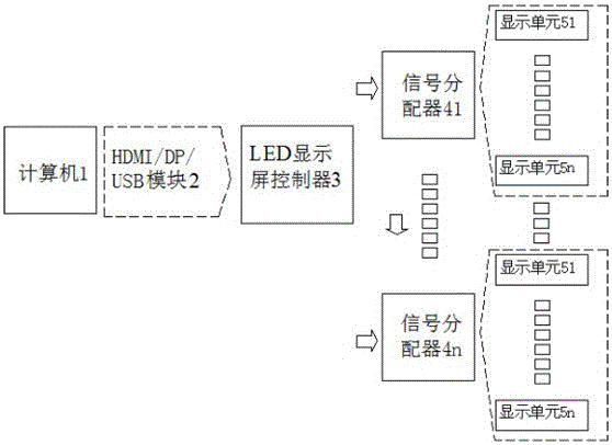
[0014] see figure 1 , the present invention provides a control architecture based on single- and bi-directional LED array display, including computer 1, HDMI / DP / USB module 2, LED display controller, signal distributor (41~4n) and display unit (51~5n) .

[0015] The computer 1 is responsible for running the control interface and playing scheme, and pre-stores and transmits video graphic information, control information program and maintenance information, and ...


PUM


Abstract

The invention discloses a control framework based on unidirectional and bidirectional LED arrangement display. The control framework includes a computer, an HDMI / DP / USB module, an LED display controller, a signal distributor and a display unit. The output end of the LED display screen controller is connected to the input end of the signal distributor, and the LED display screen controller receives video image-text information, control information programs and overhaul information transmitted from the HDMI / DP / USB module, and processes the information. The output end of the signal distributor is connected to the display unit, and the signal distributor is used for distributing the video image-text information, the control information programs and overhaul information processed by the LED display screen controller to the display unit according to the need. The control framework based on the unidirectional and bidirectional LED arrangement display changes a display of a computer into an LED display screen for display, outputs a video to the LED display screen after scaling processing, and no change of the resolution ratio of the LED display screen is needed.

Description

technical field [0001] The invention belongs to the field of LED display screens, and specifically relates to a control framework based on a single-bidirectional LED array display. Background technique [0002] Existing LED display screens use sending and receiving methods to process video, text, and picture information. The sending card receives the video, text, and picture information transmitted from the computer through the DVI interface, and pre-writes the information through the programmable logic gate array of the sending card. Enter the connection relationship information map of the receiving card to allocate the information of each receiving card. The sending card needs to send graphic information, brightness information, grayscale information and other information to the receiving card for processing. The sending card and the computer display are in a copy relationship. The resolution that the DVI interface can transmit is 1920X1080, which is limited by the resolut...

Claims


Application Information

Patent Timeline
Patent Type & Authority Applications(China)
IPC IPC(8): G09G3/32
CPCG09G3/32
Inventor 杨培典曾广立
Owner CHANGSHA XINYUAN ELECTRONICS TECH
Learn More