
Fiber distance measurement device with high sensitivity

A distance measuring device and sensitivity technology, which is applied in the field of optical fiber sensing and ranging, can solve the problems of low measurement accuracy and large error, and achieve the effects of improving application range, accuracy and high sensitivity

Inactive Publication Date: 2019-11-22
XIAN TECH UNIV
View PDF6 Cites 0 Cited by
  • Summary
  • Abstract
  • Description
  • Claims
  • Application Information

AI Technical Summary

Problems solved by technology

[0007] The invention proposes a high-sensitivity optical fiber ranging device to overcome the problems of large errors and low measurement accuracy in the prior art

Method used


Image

  • Fiber distance measurement device with high sensitivity
  • Fiber distance measurement device with high sensitivity
  • Fiber distance measurement device with high sensitivity

Examples


Embodiment Construction

[0020] The present invention will be described in detail below with reference to the drawings and embodiments.

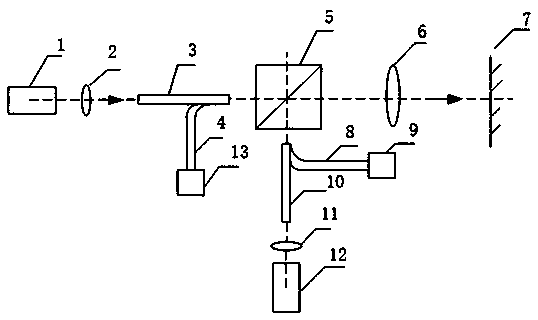
[0021] see figure 1 , a high-sensitivity optical fiber ranging device provided by the present invention consists of a first laser 1, a second laser 12, a first focusing collimating lens 2, an imaging lens 6, a second focusing collimating lens 11, the first Sending optical fiber 3, the second sending optical fiber 10, the first receiving optical fiber 4, the second receiving optical fiber 8, the filter beam splitter 5, the second photoelectric receiver 9, the first photoelectric receiver 13, the first photoelectric receiver 13 after the frequency modulation A laser 1 and a second laser 12 emit two beams of laser light with similar wavelengths respectively, and enter the first sending optical fiber 3 and the second sending optical fiber 10 through the first collimating and focusing lens 2 and the second collimating and focusing lens 11 respectively. The light emitted...


PUM


Abstract

The invention relates to the technical field of fiber sensing distance measurement and particularly relates to a fiber distance measurement device with high sensitivity. The device is composed of a first laser device, a second laser device, a first condensing collimating lens, an imaging lens, a second condensing collimating lens, a first sending fiber, a second sending fiber, a first receiving fiber, a second receiving fiber, a filtering spectroscope, a second photoelectric receiver and a first photoelectric receiver. The first laser device and the second laser device subjected to frequency modulation emit lasers with similar wavelengths respectively, the lasers enter the first sending fiber and the second sending fiber through the first collimating focusing lens and the second collimating focusing lens respectively, the light emitted by the first sending fiber is totally transmitted through the filtering spectroscope, the light emitted by the second sending fiber is totally reflectedby the filtering spectroscope, the transmission light and the reflection light are emitted to a measured object through the imaging lens, are reflected by the measured object, return along the same path and are respectively received by the first photoelectric receiver and the second photoelectric receiver, and end faces of the first transmitting fiber and the second transmitting fiber are imagedby the imaging lens in front of the measured object.

Description

Technical field: [0001] The invention relates to the technical field of optical fiber sensing and ranging, in particular to an optical fiber ranging device with high sensitivity. Background technique: [0002] With the rapid development of optical fiber technology, the theory of optical fiber is continuously deepened, and the manufacturing process of optical fiber is becoming more and more perfect. Because optical fiber has the advantages of low loss, small size, light weight, low cost, waterproof, fireproof, corrosion resistance, anti-electromagnetic interference, etc., optical fiber sensors have advantages that traditional sensors cannot match. At present, nearly a hundred sensors for measuring physical quantities such as displacement, magnetic field, electric field, voltage, temperature, sound field, and flow have been developed. The invention realizes the measurement of the displacement of the measured object. [0003] At present, the sensors for displacement measureme...

Claims


Application Information

Patent Timeline
Patent Type & Authority Applications(China)
IPC IPC(8): G01B11/02G01S17/08G01S7/481
CPCG01B11/02G01S7/4818G01S17/08
Inventor 弥谦员康
Owner XIAN TECH UNIV
Learn More