Friction locking type magnetic lifter and control method thereof

A control method and lifter technology, applied in the field of friction-locking magnetic lifters, can solve the problems of stuck moving parts, small fitting gaps between parts, small guide gaps between mover components and sealing shells, etc., and achieve high reliability , the effect of not easy to get stuck

Active Publication Date: 2017-02-15
NUCLEAR POWER INSTITUTE OF CHINA
View PDF9 Cites 4 Cited by
  • Summary
  • Abstract
  • Description
  • Claims
  • Application Information

AI Technical Summary

Problems solved by technology

[0003] At present, the control rod driving mechanism generally relies on hooks or other parts with similar functions to lock the driving rod connected to the control rod assembly or other parts with similar functions, and then moves the driving rod up and down through electromagnetic force or water pressure, such as The control rod drive mechanism described in patents CN 101178946A, CN 1256497A, and CN 1442863A needs to rely on the hook to lock the drive rod, so it has high requirements for the wear of moving parts. Once the wear of the hook or other parts is large, it may As a result, the control rod drive mechanism cannot normally lift and insert the control rod assembly, and because the fitting clearance of the parts is small, the moving parts are prone to jamming due to the entry of impurities or other reasons, which may affect the normal drop of the control rod drive mechanism
Patent CN 102956274A is based on the principle of linear reluctance motor. Although it directly converts electric energy into linear electromagnetic thrust to drive the mover assembly connected to the control rod assembly to move up and down, but due to the high guiding requirements for the mover assembly to reduce The magnetic bias pull force, the guide gap between the mover assembly and the sealing shell is small, correspondingly, there are high requirements for the wear of moving parts, and it is also easy to cause sticking due to impurities or other reasons.

Method used


Image

  • Friction locking type magnetic lifter and control method thereof
  • Friction locking type magnetic lifter and control method thereof
  • Friction locking type magnetic lifter and control method thereof

Examples


Embodiment 1

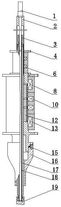
[0048] Such as figure 1 A friction-locking magnetic lifter is shown, comprising a sealing case 2, a driving rod assembly and an armature 12 all located in the sealing case 2, and the driving rod assembly includes a friction rod 17; The armature housing cavity where the shaft of the rod 17 moves, the armature 12 is placed in the armature housing cavity; the sealing shell 2 is provided with a holding assembly, a moving assembly and a lifting assembly outside, and the holding assembly, the moving assembly, and the lifting assembly all include a yoke and are installed on the yoke The internal coil, the electromagnetic force generated after the coil 6 of the holding component is energized makes the friction rod 17 close to the sealing shell 2, the electromagnetic force generated after the coil 10 of the moving component is energized makes the friction rod 17 close to the armature 12, and the coil 8 of the lifting component The electromagnetic force generated after electrification d...

Embodiment 2

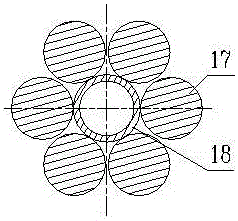
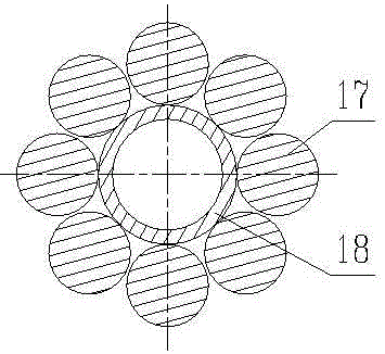
[0070] This embodiment is refined on the basis of the above-mentioned embodiment, that is, the drive rod assembly also includes a core rod 18 and a plurality of friction rods, and a plurality of friction rods 17 are arranged in parallel with the core rod 18 and surround the core rod 18, as Figure 2 to Figure 7 It is a radial cross-sectional view of six different core rods 18 and friction rods 17; the two ends of the core rod 18 and friction rod 17 are respectively provided with a magnetic block 3 and a control rod connecting rod 19 for fixing and limiting the two. The rod connecting rod is connected with the control rod assembly; the rod position detector 1 is installed on the sealed shell 2, and the rod position detector 1 detects the position of the magnetic block 3 to obtain the actual position of the driving rod assembly and the control rod assembly connected to it .

[0071] The rod position detector 1 can be arranged on the top of the sealed casing, and inserted into th...

Embodiment 3

[0074] An elastic component 20 that can drive the armature 12 to move down along the axis of the drive rod assembly is arranged in the sealing shell 2 . The elastic member is preferably a spring, and the spring has a downward force on the armature, which can accelerate the downward movement of the armature and ensure the stability of the armature and drive rod assembly in the control step.


PUM


Abstract

The invention discloses a friction locking type magnetic lifter and a control method thereof. The lifter comprises a sealed casing as well as a drive rod assembly and an armature which are located in the sealed casing, wherein the drive rod assembly comprises a friction rod; an armature accommodating cavity for the armature to axially move along the friction rod conveniently is formed between the drive rod assembly and the sealed casing, a retaining assembly for enabling the friction rod to be closely attached to the sealed casing, a moving assembly for enabling the friction rod to be closely attached to the armature and a lifting assembly for driving the armature to move upwards along the friction rod are arranged on the sealed casing, and each of the retaining assembly, the moving assembly and the lifting assembly comprises a magnetic yoke and a coil winding around the magnetic yoke. The lifter adopting the structure is large in wear allowance and high in rod falling reliability.

Description

technical field [0001] The invention relates to the field of nuclear reactor control rod driving mechanism, in particular to a novel control rod driving mechanism, namely a friction locking type magnetic lifter. Background technique [0002] The control rod drive mechanism is the servo mechanism of the nuclear reactor control and protection system. It needs to lift, insert, hold and release the control rod assembly according to the command, so as to complete the reactor start-up, power adjustment, power maintenance, normal shutdown and safety shutdown. Among the published invention patents are stepping magnetic lift type reactor control rod drive mechanism, fully enclosed movable coil electromagnet control rod drive mechanism, water pressure driven control rod drive mechanism, hybrid linear reluctance motor type control rod Control rod drive mechanism with various principles such as drive mechanism. [0003] At present, the control rod driving mechanism generally relies on ...

Claims


Application Information

Patent Timeline
Patent Type & Authority Applications(China)
IPC IPC(8): G21C7/12G21C7/14
CPCG21C7/12G21C7/14Y02E30/30
Inventor 杨方亮杨晓晨邓强罗英陈西南彭航唐向东李维张智峰杨博于天达胥春燕刘佳晋舒颜
Owner NUCLEAR POWER INSTITUTE OF CHINA
Why Eureka
Try Eureka