Inductive coil automatic assembling and bending device and method

An automatic assembly and inductance coil technology, which is applied in coil manufacturing, inductance/transformer/magnet manufacturing, circuits, etc., can solve the problems of increasing the possibility of damage to the inductance coil, high labor intensity, and reducing the service life of the product, so as to avoid Unstable fixation, less influence of artificial factors, and improved processing efficiency

Active Publication Date: 2017-02-15
新井田智能装备(江苏)有限公司
View PDF5 Cites 7 Cited by
  • Summary
  • Abstract
  • Description
  • Claims
  • Application Information

AI Technical Summary

Problems solved by technology

[0003] When processing an inductance coil containing an iron core or a magnetic powder core, it is necessary to fix the iron core or magnetic powder core in the central through hole of the coil. If the existing fixing method is to manually dispense glue on the surface of the iron core or magnetic powder core, then Manual insertion into the coil, but the manual method is not only inefficient and labor-intensive, but also often cannot guarantee the quality of dispensing, plugging, and fixing. The standardization level of products is greatly reduced, and the consistency of product quality cannot be guaranteed, and the inductance is increased. The possibility of damage to the coil during use, reducing the service life of the product
[0004] In addition, because glue is used for bonding, the connection between the iron core or magnetic powder core and the coil is not firm enough, and it is prone to loosening and separation in environments such as impact and high temperature.

Method used


Image

  • Inductive coil automatic assembling and bending device and method
  • Inductive coil automatic assembling and bending device and method
  • Inductive coil automatic assembling and bending device and method

Examples


Embodiment Construction

[0044] Objects, advantages and features of the present invention will be illustrated and explained by the following non-limiting description of preferred embodiments. These embodiments are only typical examples of applying the technical solutions of the present invention, and all technical solutions formed by adopting equivalent replacements or equivalent transformations fall within the protection scope of the present invention.

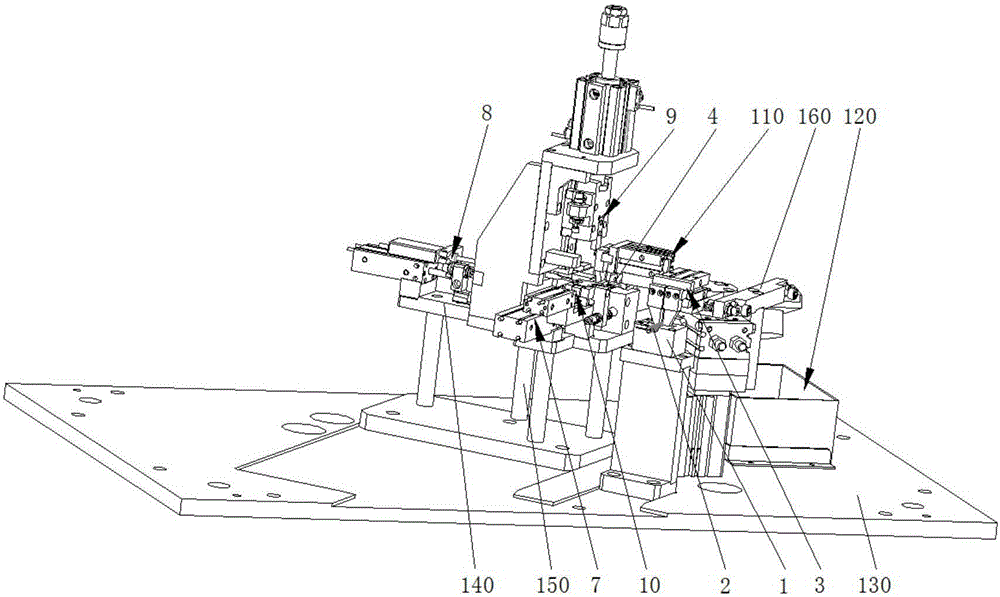
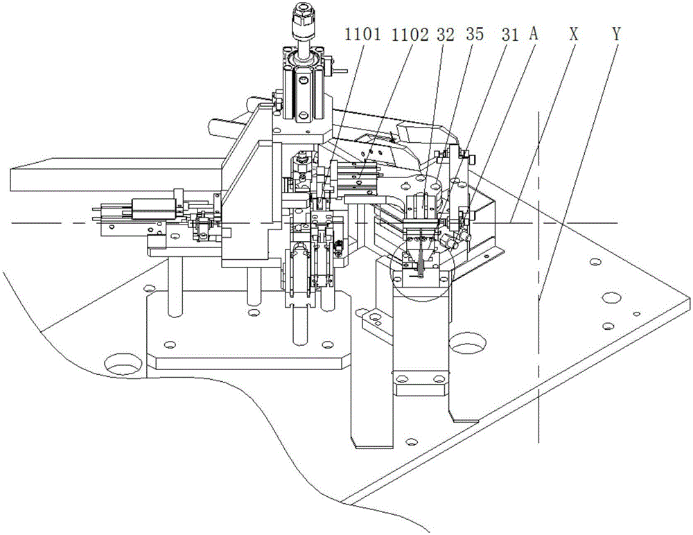
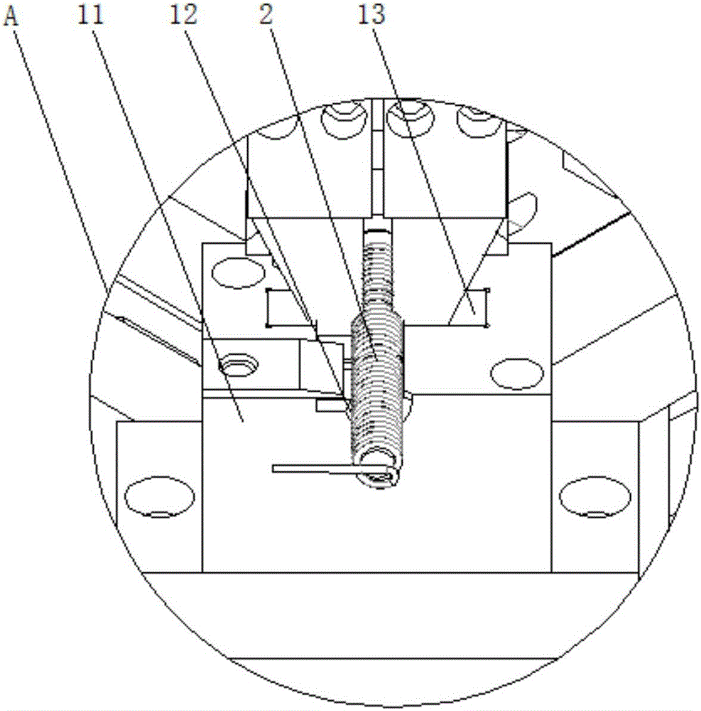
[0045] The inductance coil automatic assembly and bending equipment disclosed by the present invention is as attached figure 1 , attached Figure 5 As shown, it includes a bottom plate 130, and the bottom plate 130 is provided with a position-matched first coil positioning block 1, a coil moving mechanism 3, a second coil positioning block 4, a magnetic core transmission line 5, a dislocation mechanism 7, and a magnetic core pushing mechanism 8. A coil bending mechanism 9 , a coil pressing mechanism 10 , and a blanking mechanism 110 .

[0046] Wher...


PUM


Abstract

The invention discloses an inductive coil automatic assembling and bending device and method. The inductive coil automatic assembling and bending device comprises a first coil positioning block used for placement of a coil; a coil moving mechanism used for moving the coil on the first coil positioning block to a second coil positioning block; a magnetic core conveying line used for providing a magnetic core; a dislocating mechanism used for containing the magnetic core conveyed by the magnetic core conveying line and enabling the magnetic core to be aligned to or staggered with the coil; a magnetic core conveying mechanism used for pushing the magnetic core into the coil when the magnetic core on the dislocating mechanism is aligned to the coil on the second coil positioning block; a coil bending mechanism used for down-pressing a wire at the opening end of the coil on the dislocating mechanism and enabling the bending part to block the opening end; a coil pressing mechanism used for limiting the coil to the second coil positioning block; and a discharging mechanism used for moving the electromagnetic coil finished processing on the second coil positioning block into a product region. The inductive coil automatic assembling and bending device avoids the problem of unstable fixation of the coil and the magnetic core caused by gluing, is high in degree of automation and greatly increases the processing efficiency.

Description

technical field [0001] The invention relates to the field of automation equipment, in particular to an induction coil automatic assembly bending equipment and a method thereof. Background technique [0002] The inductance coil is a device that uses the principle of electromagnetic induction to work. It is made of wires that are wound around an insulating tube. The wires are insulated from each other, and the insulating tube can be hollow or contain an iron core or a magnetic powder core. . [0003] When processing an inductance coil containing an iron core or a magnetic powder core, it is necessary to fix the iron core or magnetic powder core in the central through hole of the coil. If the existing fixing method is to manually dispense glue on the surface of the iron core or magnetic powder core, then Manual insertion into the coil, but the manual method is not only inefficient and labor-intensive, but also often cannot guarantee the quality of dispensing, plugging, and fix...

Claims


Application Information

Patent Timeline
Patent Type & Authority Applications(China)
IPC IPC(8): H01F41/00H01F41/04
CPCH01F41/00H01F41/04
Inventor 王越
Owner 新井田智能装备(江苏)有限公司
Why Eureka
Try Eureka