Tin rinsing device for wire connector

A technology for wire joints and equipment, applied in circuits, connections, electrical components, etc., can solve the problems of poor wire joints, inconvenience for tinning personnel, and easy heating of wires, so as to improve the efficiency of tinning work, save time, The effect of a high degree of automation

Active Publication Date: 2017-02-15
JINAN CITY CHANGQING DISTRICT POWER SUPPLY CO OF STATE GRID SHANDONG ELECTRIC POWER CO +1
View PDF5 Cites 6 Cited by
  • Summary
  • Abstract
  • Description
  • Claims
  • Application Information

AI Technical Summary

Problems solved by technology

[0002] At present, in the maintenance and repair process of the line, it is often necessary to connect two strands of electric wires, and the wire joints are sometimes easily connected incorrectly, and the wires at the joints are prone to heat, and then heated and oxidized. In the prior art, the staff It is usually necessary to rinse tin at the wire joints to prevent oxidation, but most of them still require the staff to manually operate one by one. The steps are cumbersome and the workload is too heavy, which is very inconvenient for tinning personnel.

Method used


Image

  • Tin rinsing device for wire connector
  • Tin rinsing device for wire connector
  • Tin rinsing device for wire connector

Examples


Embodiment Construction

[0041] In order to better understand the present invention, the implementation manner of the present invention will be explained in detail below in conjunction with the accompanying drawings.

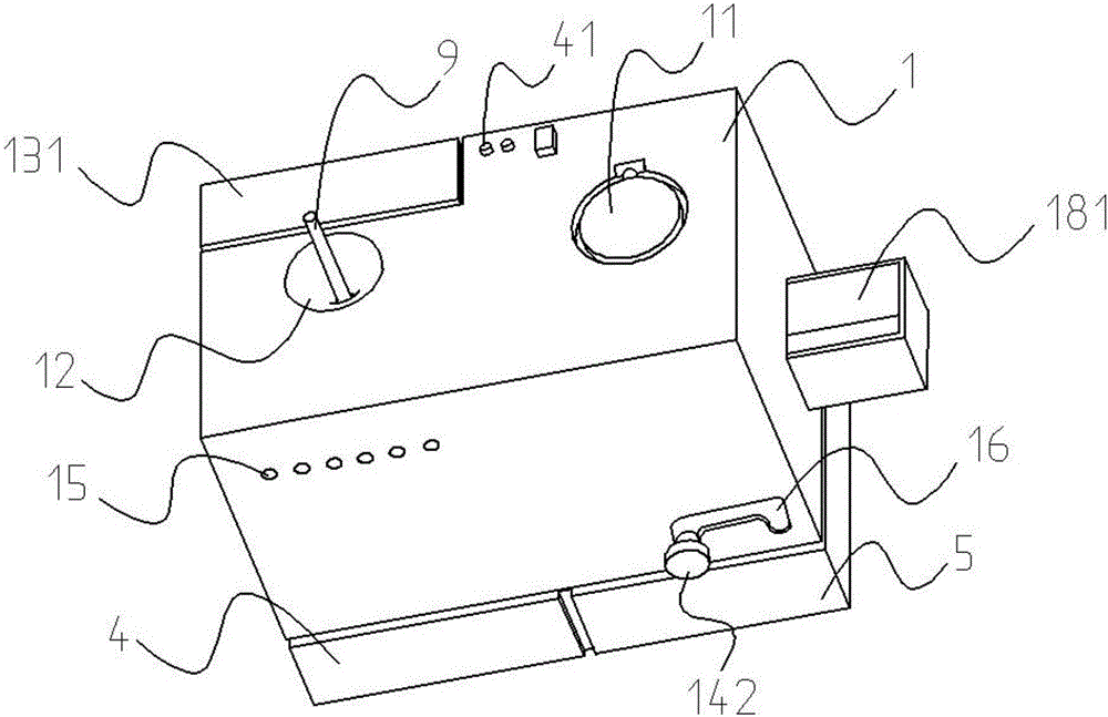
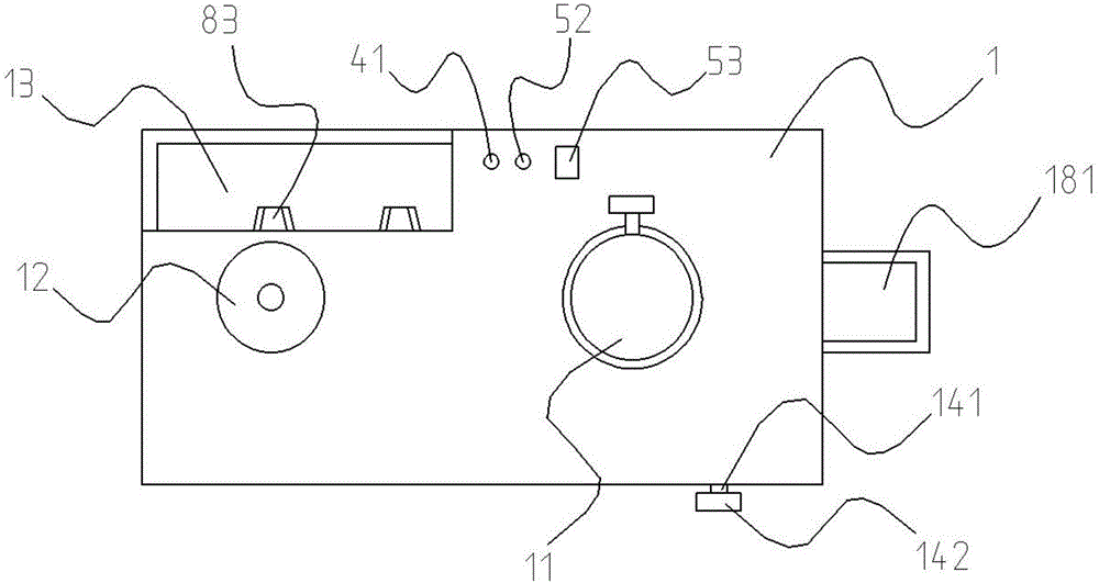
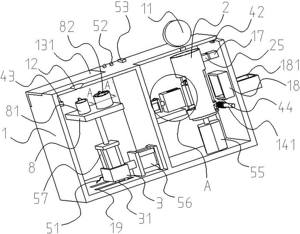
[0042] Such as Figure 1 to Figure 14 As shown in the figure, a tinning equipment for wire joints includes a shell 1, a peeling cover 11, a tinning opening 12, a feeding opening 13, a feeding opening cover 131, a bull's-eye bearing 14, a worm 141, a fixed knob 142, and a cooling hole 15, n-shaped track 16, magnet one 17, outlet lenticels 18, wire sheath holding groove 181, pulley rail 19, rotating sleeve 2, rectangular through hole 21, turbine hole 22, spring fixing frame one 23, spring 231, fulcrum Body 24, magnet two 25, lever body 26, spring fixing frame two 261, fulcrum rotating column 262, sliding column 263, supporting body 3, roller 31, controller 4, completion indicator light 41, infrared sensor one 42, infrared sensor two 43. Infrared sensor three 44, mobile power supply 5, co...


PUM


Abstract

The invention provides a tin rinsing device for wire connector, which belongs to the technical field of tin rinsing devices. The device of the invention comprises a shell. The bottom of the shell is provided with a controller and a mobile power supply respectively. The left side and the right side at the top of the shell are provided with a skin removing mouth cover and a tin rinsing mouth respectively. The lower part of the skin removing mouth cover faces right a cylindrical rotation sleeve. The inner wall of the rotation sleeve is fixedly provided with six fulcrum bodies distributed in uniform manner. The lower part of the tin rinsing mouth corresponding to one side at the bottom of a separation cavity is provided with a cylinder (2). The cylinder (2) is connected with a support body. The top of the support body is provided with a cylinder (3). The cylinder (3) is connected with a fixed plate. The left side and the right side of the fixed plate are fixedly provided with a solution tank and a tin solution tank respectively. The circumference of the tin solution tank and the bottom are provided with heat isolation plates. The bottom of the tin solution tank is further provided with an electric heating plate. The tin rinsing device of the invention is highly automatic and practical in use. With the device, the problem can be resolved that in the prior art, tin rinsing efficiency for the wire connector is low. In the working process, time can be saved; labor intensity can be reduced; these advantages made the device a very good one with strong practicability in use.

Description

technical field [0001] The invention relates to the technical field of tinning equipment, in particular to a tinning equipment for electric wire joints. Background technique [0002] At present, in the maintenance and repair process of the line, it is often necessary to connect two strands of electric wires, and the wire joints are sometimes easily connected incorrectly, and the wires at the joints are prone to heat, and then heated and oxidized. In the prior art, the staff It is usually necessary to rinse tin at the wire joints to prevent oxidation, but most of them still require the staff to manually operate one by one. The steps are cumbersome and the workload is too heavy, which is very inconvenient for tinning personnel. Therefore we urgently need a kind of easy-to-use, high degree of automation, and practical electric wire connector tin-washing equipment simultaneously. Contents of the invention [0003] The present invention aims at the deficiencies of the above-me...

Claims


Application Information

Patent Timeline
Patent Type & Authority Applications(China)
IPC IPC(8): H01R43/02
CPCH01R43/0235
Inventor 李军李文博李红玲雒天宁王昭军王娜张令燕张娟
Owner JINAN CITY CHANGQING DISTRICT POWER SUPPLY CO OF STATE GRID SHANDONG ELECTRIC POWER CO
Why Eureka
Try Eureka