A non-rectifier bridge power-taking circuit

A technology without a rectifier bridge and circuit, applied in circuit devices, electrical components, etc., can solve problems such as multi-level loss, and achieve the effects of low power consumption, miniaturization, and wide operating range

Active Publication Date: 2019-03-29
ELECTRIC POWER RES INST OF GUANGDONG POWER GRID
View PDF6 Cites 0 Cited by
  • Summary
  • Abstract
  • Description
  • Claims
  • Application Information

AI Technical Summary

Problems solved by technology

[0005] The embodiment of the present invention discloses a rectification bridge-free power-taking circuit, which constitutes a rectification change circuit without a rectification bridge through a MOS tube and a diode, which solves the problems caused by multiple energy conversions in the rectification conversion circuit with a rectification bridge in the prior art. Technical Issues of Multi-stage Loss

Method used


Image

  • A non-rectifier bridge power-taking circuit
  • A non-rectifier bridge power-taking circuit
  • A non-rectifier bridge power-taking circuit

Examples


Embodiment Construction

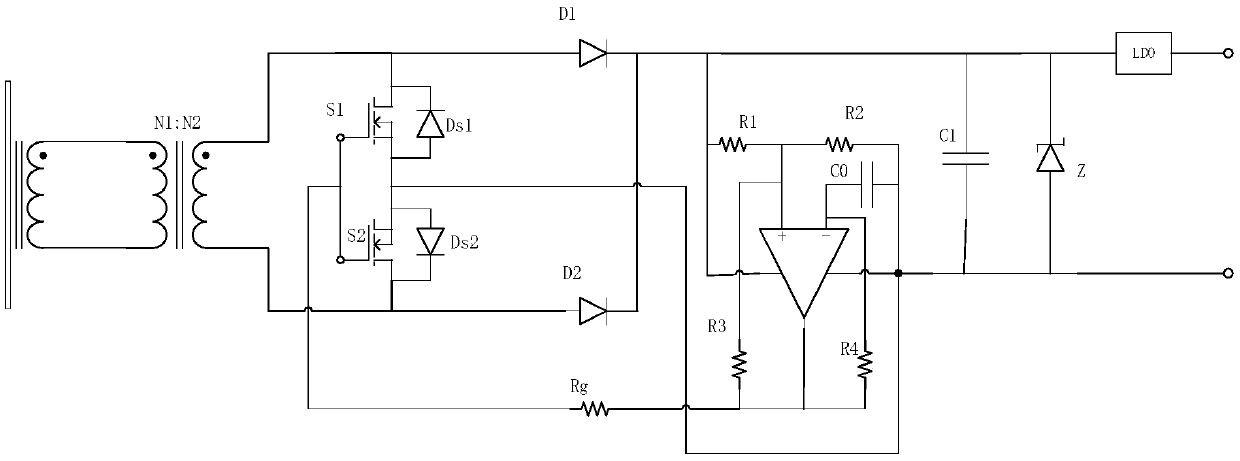
[0038] The embodiment of the present invention discloses a rectification bridge-free power-taking circuit, which constitutes a rectification change circuit without a rectification bridge through a MOS tube and a diode, which solves the problems caused by multiple energy conversions in the rectification conversion circuit with a rectification bridge in the prior art. The technical problem of multi-stage loss.

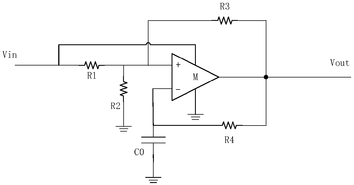
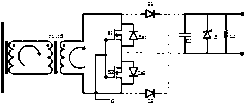
[0039] see Figure 1 to Figure 2 , an embodiment of a rectifier bridge-free power-taking circuit provided in an embodiment of the present invention includes: a power-taking and boosting module, a rectifying module electrically connected to the power-taking and boosting module, a filter stabilizer electrically connected to the rectifying module pressure module;

[0040] The rectification module specifically includes: a first MOS transistor S1, a second MOS transistor S2, a first diode Ds1, a second diode Ds2, a third diode D1, and a fourth diode D2;

[0041] The sources...


PUM


Abstract

The embodiment of the invention discloses a rectifier-bridge-free power-taking circuit formed by using MOS tubes and diodes. With the provided circuit, a technical problem of multi-stage losses caused by energy conversation at multiple places in the rectifier-bridge-included rectification conversion circuit in the prior art can be solved. The rectifier-bridge-free power-taking circuit comprises a power-taking boost module, a rectification module connected with the power-taking boost module electrically, and a filter and voltage-stabilizing module connected with the rectifier module electrically. The rectification module consists of a first MOS tube S1, a second MOS tube S2, a first diode Ds1, a second diode Ds2, a third diode D1, and a fourth diode D2.

Description

technical field [0001] The invention relates to the field of inductive power taking, in particular to a rectifying bridge-free power taking circuit. Background technique [0002] With the continuous improvement of the power industry, there are more and more online monitoring equipment working on transmission and distribution lines. The power supply is one of the key issues when conducting on-line monitoring of transmission lines. The most commonly used power supply method for online monitoring equipment of power systems is inductive energy harvesting power supply. This method collects the energy in the electromagnetic field around the line through the energy harvesting core, and then converts the AC signal on the secondary side into a stable DC signal through the rectification conversion circuit. Powers the microprocessor and communication unit. [0003] The rectification conversion circuit in the existing induction power-taking method all adopts a rectification module wit...

Claims


Application Information

Patent Timeline
Patent Type & Authority Patents(China)
IPC IPC(8): H02J5/00H02J50/12
CPCH02J5/005
Inventor 李传健宋旭东靳一林张晓平陈小军李书杰黄曙邓应松陈辉郑文杰孙健
Owner ELECTRIC POWER RES INST OF GUANGDONG POWER GRID
Why Eureka
Try Eureka