Self-enforced bidirectional high-voltage gain interleaved switched reluctance motor power converter system

A technology of switched reluctance motor and power converter, which is applied to AC motor control, output power conversion device, and control of generator through magnetic field changes, etc., can solve the problems of reduced reliability, short excitation current time, complex structure, etc. Achieve the effect of saving consumption, reducing cost and simplifying structure

Active Publication Date: 2019-09-10
CHINA JILIANG UNIV
View PDF5 Cites 0 Cited by
  • Summary
  • Abstract
  • Description
  • Claims
  • Application Information

AI Technical Summary

Problems solved by technology

[0005] In the excitation control of switched reluctance generators, the strengthening of the excitation phase is a hot research topic in recent years. The most typical example is the Z-source network converter proposed by Professor Peng Fangzheng. There are also other strengthening methods in the industry, such as these, most of them rely on separately increasing the external circuit to strengthen and increase the excitation voltage, so that the excitation current in the excitation phase rises faster and the time is shorter, and then there is a larger phase current before the power generation phase begins, and relatively more The wide power generation stage range makes the difference between the output electric energy in the power generation stage minus the electric energy consumed in the excitation stage is larger, that is, the output power is larger, but the external strengthening of the excitation circuit will inevitably make the structure complex, increase the complexity of the control, and reduce the reliability. sex
[0006] As for the starting solution of the switched reluctance generator, the industry often adds a battery series diode branch in front of the main circuit of the power converter. Large, it is necessary to check the power of the battery from time to time and replace the battery or charge it manually, which increases the cost of operation and maintenance
[0007] At present, in some fields, including the fields where switched reluctance motors have been applied, they will be required to adapt to the dual-mode operation of electric / power generation according to needs, that is, they can be operated as generators according to instructions, and can also be switched to motor conditions according to needs. If When the motor and generator are running, different power converters are used and switched according to needs, which will inevitably greatly increase the complexity of the structure. Therefore, the same set of power converters can flow bidirectional electric energy and ensure electric / generating operation, which will be very useful. future
[0008] As a switched reluctance generator, for example, as a power generation supply device in a microgrid network, or as a power supply for high-voltage load devices, the generated voltage directly output by the switched reluctance generator through the traditional power converter system is often too low to meet the requirements of the output side. Therefore, if the boost function is taken into account in the power converter system, the structure will inevitably be simplified

Method used


Image

  • Self-enforced bidirectional high-voltage gain interleaved switched reluctance motor power converter system

Examples


Embodiment Construction

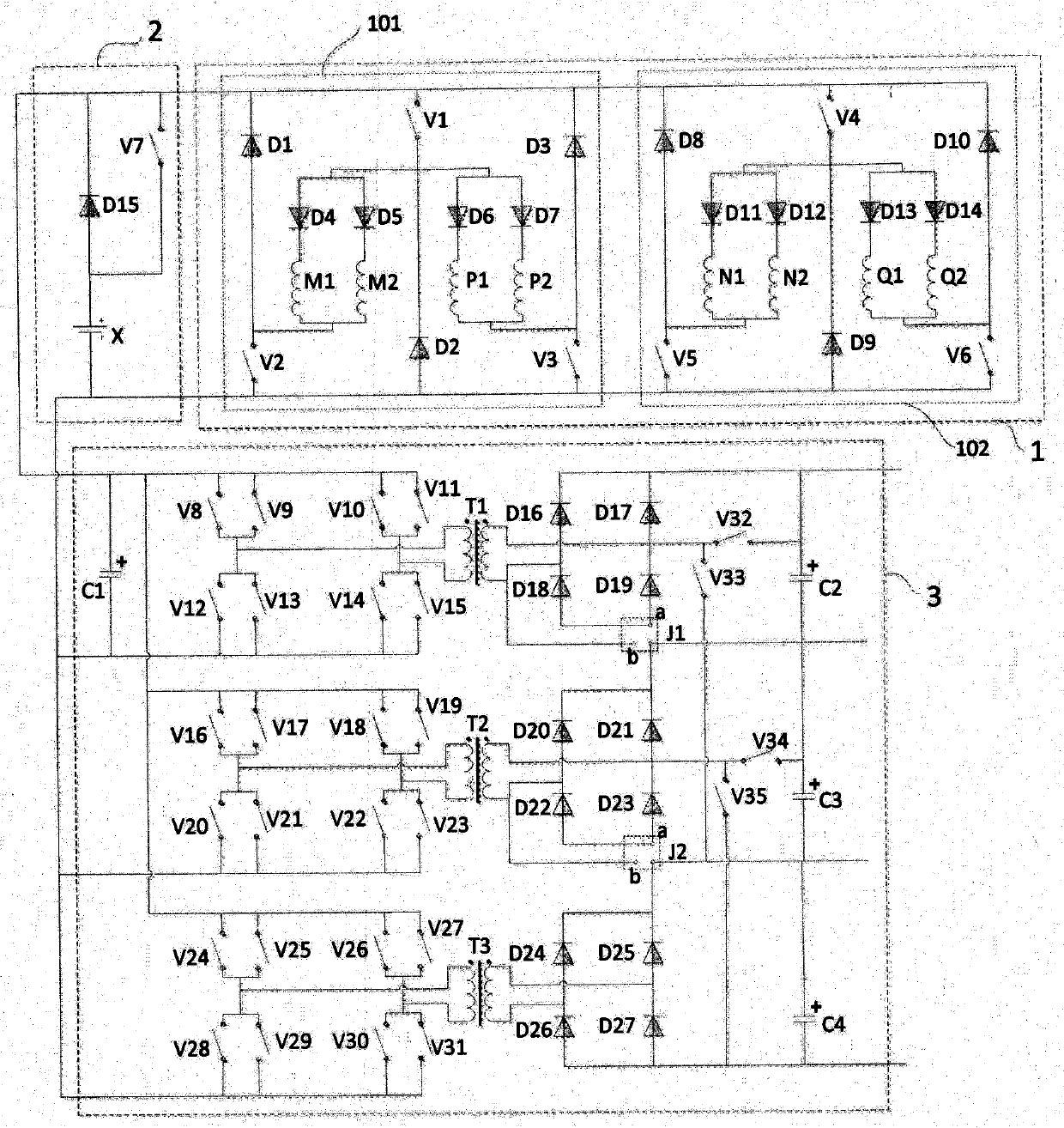
[0038] The switched reluctance generator of this embodiment is a four-phase winding, which is respectively M / N / P / Q four-phase windings according to the order distributed on the stator, and each phase winding is divided into two branch windings wound on different symmetrical On the salient poles of the stator, and connected in parallel through diodes in series, the structure of the power converter system is shown in the attached figure 1 shown.

[0039] Self-forced bidirectional high-voltage gain interleaved switched reluctance motor power converter system, composed of main circuit 1, excitation power supply 2, bidirectional DC-AC-DC3, main circuit 1, excitation power supply 2, bidirectional DC-AC-DC3 are connected to each other ;

[0040] The main circuit 1 is composed of a first main circuit 101 and a second main circuit 102, and the first main circuit 101 and the second main circuit 102 are connected in parallel;

[0041] The first main circuit 101 is composed of the first...


PUM


Abstract

Self-forced bidirectional high-voltage gain interleaved switched reluctance motor power converter system, composed of main circuit, excitation power supply, bidirectional DC‑AC‑DC, the main circuit, excitation power supply, bidirectional DC‑AC‑DC are connected to each other; the main circuit reduces The amount of switching tube is reduced, and each phase winding is divided into two branches connected in parallel to obtain the technical effect of strengthening excitation, increasing power generation capacity or quick torque response; bidirectional DC‑AC‑DC ensures that the switched reluctance motor can generate power in the forward direction and reverse direction It has dual functions of direction electric and isolation, high-frequency transformation and high voltage gain. The interlaced control mode during reverse electric operation can reduce torque ripple and noise, reduce volume, and improve adaptability and reliability; The system is especially suitable for the field of motor systems that require time-segmented power generation / electric operation, including variable speed switch reluctance wind power generation systems, pumped storage power station power generation-electric systems, power generation / electric systems in the automotive and aviation fields, etc.

Description

technical field [0001] The invention relates to the field of motor systems, in particular to a switched reluctance motor power converter system for both power generation and electric motoring and a control method thereof. Background technique [0002] The switched reluctance motor has a simple and solid structure, low manufacturing cost, high performance in a wide speed range, no winding on the rotor, no permanent magnet, high reliability, and broad application prospects. [0003] Switched reluctance motors generally have 2-5 phase windings placed on the stator, and the phase windings that are energized are determined according to the relative position of the salient poles between the stator and rotor; when operating as a generator, it is slightly complicated, and each phase winding generally needs to be divided It is two stages of excitation and power generation. In the excitation stage, the phase winding of the motor absorbs the electric energy of the external excitation p...

Claims


Application Information

Patent Timeline
Patent Type & Authority Patents(China)
IPC IPC(8): H02P9/08H02P9/14H02P25/092H02P25/098H02M3/28
CPCH02M3/28H02P9/08H02P9/14H02P25/092H02P25/098H02M1/0067
Inventor 孙冠群
Owner CHINA JILIANG UNIV
Why Eureka
Try Eureka