
A vibration motor grounding structure and automobile

A vibration motor and grounding structure technology, applied in the direction of connection with grounding devices, can solve problems such as poor contact, difficult assembly, and high assembly accuracy requirements, and achieve the effects of stable grounding effect, simple structure and reliable contact.

Active Publication Date: 2019-04-23
合肥唯真电机有限公司
View PDF5 Cites 0 Cited by
  • Summary
  • Abstract
  • Description
  • Claims
  • Application Information

AI Technical Summary

Problems solved by technology

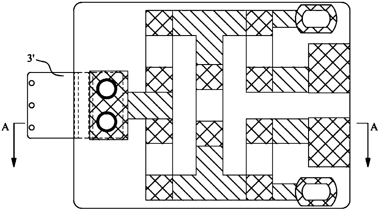
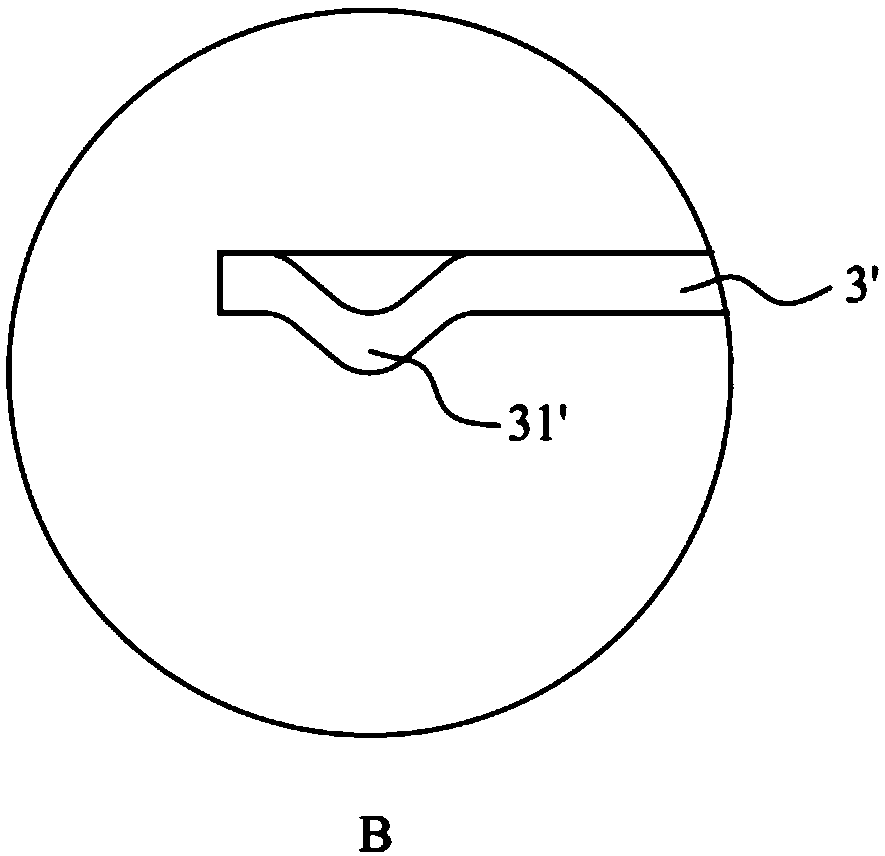
[0003] However, in this grounding structure, only one end of the PCB board 4' is fixed to the vibrating motor. When the vibrating motor vibrates, it will drive the PCB board 4' to vibrate, thereby causing the metal connector 3' connected to the other end of the PCB board 4' to vibrate. , because the metal connector 3' has no other fixed structure, the contact between the metal connector 3' and the shell of the vibration motor cannot be guaranteed, and a stable grounding effect cannot be guaranteed; in addition, the metal connector 3' only connects with the vibration motor through an arc-shaped arc surface. This grounding structure requires high assembly accuracy of the PCB board 4' and the metal connector 3'. When the error is large, it is easy to cause the bumps to fail to contact the shell of the vibration motor, which is difficult to assemble.

Method used


Image

  • A vibration motor grounding structure and automobile
  • A vibration motor grounding structure and automobile
  • A vibration motor grounding structure and automobile

Examples


Embodiment 1

[0040] Such as Figure 7-17 As shown, this embodiment provides a grounding structure for a vibration motor, including a metal bracket 2, a vibration motor, and a metal connector 3. The vibration motor includes a motor body 1 and a PCB board 4 electrically connected to the terminals of the motor body 1. 1 is fixed to the metal bracket 2, the PCB board 4 is used to control the vibration of the vibration motor body 1; the metal bracket 2 is provided with a connection hole; one end of the PCB board 4 is the connection end, the metal connection piece 3 is fixed to the connection end, the metal connection piece 3 A resilient piece 31 protruding outward is provided, and the connecting end and the metal connector 3 extend into the connecting hole, and the resilient piece 31 and the connecting end respectively abut the inner wall of the connecting hole to realize the design of the vibration motor grounding.

[0041] Compared with the prior art, the metal bracket 2 in this embodiment is pro...

Embodiment 2

[0046] This embodiment provides an automobile, including a steering wheel, and the grounding structure of the vibration motor provided in Embodiment 1 is provided in the steering wheel. Compared with the prior art contacting the shell of the vibration motor through the bump 31' on the metal connector 3', the metal connector 3 in the grounding structure of the vibration motor has a reliable contact with the metal bracket 2, and the motor is grounded. The effect is stable, and the structure of the metal connector 3 is simple and easy to assemble.


PUM


Abstract

The invention discloses a vibration motor grounding structure and an automobile. The vibration motor grounding structure comprises a metal support, a vibration motor and a metal connection piece. The vibration motor comprises a motor body and a PCB in electric connection with the motor body terminal. The motor body is fixed to the metal support and the metal support is provided with a connection hole. One end of the PCB is a connection end. The metal connection piece is fixed to the connection end. The metal connection piece is provided with an outwardly protruding elastic sheet; the connection end and the metal connection piece are inserted into the connection hole; and the elastic sheet and the connection end abut against the inner wall of the connection hole respectively. In the grounding structure, the metal connection piece and the PCB are inserted into the connection hole of the metal support; the metal connection piece and the metal support are in reliable contact. The grounding effect of the motor becomes more stable. With a simple structure, the metal connection piece is easy to assemble.

Description

Technical field [0001] The invention relates to the technical field of motors, in particular to a vibration motor grounding structure and automobiles. Background technique [0002] The vehicle steering wheel vibration motor requires good grounding and good electromagnetic compatibility (Electro Magnetic Compatibility, EMC), and the electronic components on the PCB board must be designed with a grounding structure. In the existing technology, such as Figure 1-Figure 6 As shown, one end of the PCB board 4'is electrically connected to the terminal on the vibration motor, and the other end is connected with a metal connector 3'. The metal connector 3'is generally a stepped connector. Among the two parallel ends, one end is connected to PCB board 4'is fixedly connected, and the shell of the vibration motor at the other end is in contact to achieve the grounding effect. The end of the metal connector 3'that is in contact with the vibration motor protrudes toward the housing of the vib...

Claims


Application Information

Patent Timeline
Patent Type & Authority Patents(China)
IPC IPC(8): H02K11/40
Inventor 单瑜彤刘承威罗志伟
Owner 合肥唯真电机有限公司
Learn More