Omnidirectional tracking photovoltaic power generation equipment

A photovoltaic power generation equipment and all-round technology, applied in photovoltaic power generation, photovoltaic modules, solar thermal power generation, etc., can solve the problems of photovoltaic power generation equipment being difficult to popularize, and the angle change range is large, so as to achieve good overall structure rigidity, stable and reliable support Effect

Active Publication Date: 2017-02-15
JIANGSU QIJING OPTOELECTRONICS TECH CO LTD
View PDF6 Cites 7 Cited by
  • Summary
  • Abstract
  • Description
  • Claims
  • Application Information

AI Technical Summary

Problems solved by technology

[0005] In order to improve the overall rigidity of this type of photovoltaic power generation equipment and reduce the deformation of photovoltaic modules and their mounting brackets, it is a conceivable solution to set up supports around the module mounting brackets. However, the angle of photovoltaic modules varies in a large range during daily tracking. When the edge of the component mounting bracket changes from the lowest position close to the ground to the highest position, the range of variation is close to the side length of the component mounting bracket, so the supports that provide support for the component mounting bracket must have a large range of length variation. Commonly used can be The length-adjustable support structure cannot meet the length change requirements, which is why the existing photovoltaic power generation equipment has only one independent middle column, and it is also the reason why the above-mentioned photovoltaic power generation equipment with dual-axis tracking function The root cause of the difficulty in promoting practical applications

Method used


Image

  • Omnidirectional tracking photovoltaic power generation equipment
  • Omnidirectional tracking photovoltaic power generation equipment
  • Omnidirectional tracking photovoltaic power generation equipment

Examples


Embodiment Construction

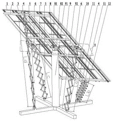
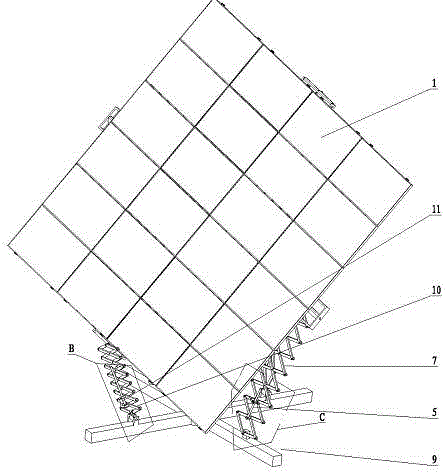
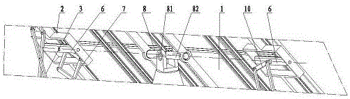
[0033] in figure 1 versus figure 2 In the omnidirectional tracking photovoltaic power generation equipment shown, the component mounting bracket 2 is a rectangular frame steel member, and the photovoltaic module 1 is installed on the component mounting bracket 2 of the rectangular frame steel member, see image 3 , The bottom center of the component mounting bracket 2 is hinged with both ends of the shaft A82 on the cross shaft 8. The shaft B81 and the shaft A82 on the cross shaft 8 intersect perpendicularly to each other, and the length of the shaft B81 is relatively shorter than the length of the shaft A82 to facilitate The component mounting bracket 2 has a relatively large angle range when rotating relative to the axis A82. The two ends of the axis B81 on the cross shaft 8 are hinged on the upright part 91 of the base 9, so that the component mounting bracket 2 is supported on the base through the cross shaft 8. On the upright part 91 of the seat 9, the base 9 includes a upr...


PUM


Abstract

The invention discloses omnidirectional tracking photovoltaic power generation equipment. The omnidirectional tracking photovoltaic power generation equipment comprises an assembly mounting bracket and a pedestal, wherein the pedestal comprises a stand column part and a base part; the assembly mounting bracket is supported on the stand column part of the pedestal through a universal joint pin; a planar telescopic supporting part and a space telescopic supporting part are arranged on the periphery of the assembly mounting bracket; at least one planar telescopic auxiliary supporting part and at least one space telescopic auxiliary supporting part are further arranged on the periphery of the assembly mounting bracket; the maximum spacing between the two ends of each telescopic supporting part in an extension state is 3.5-12m while the minimum spacing between the two ends of each telescopic supporting part in a contraction state is 0.3-1m; each of the planar telescopic supporting part and the space telescopic supporting part is provided with a tracking driving mechanism separately; and each of the planar telescopic auxiliary supporting part and the space telescopic auxiliary supporting part is provided with a length locking mechanism separately. By adoption of the omnidirectional tracking photovoltaic power generation equipment, not only the omnidirectional tracking of the sun position but also high installed capacity of a power station, reliable supporting and stable structure can be realized.

Description

Technical field [0001] The invention relates to a photovoltaic power generation equipment, in particular to a large-scale photovoltaic power station equipment capable of realizing omnidirectional tracking of the sun position. Background technique [0002] Solar energy is inexhaustible, and the use of solar energy to generate green energy through photovoltaic power generation technology has been widely used. Photovoltaic power equipment receives solar energy to generate electricity, and its power generation is directly related to the amount of solar radiation received. Compared with fixed-installed photovoltaic power plant equipment, photovoltaic power plant equipment with tracking function can track the sun's position and Make the light-receiving surface of the photovoltaic module as vertical as possible to the sun's rays, and the result is obviously that the maximum solar radiation can be obtained, and thus the maximum power generation can be obtained. [0003] The sun rises from...

Claims


Application Information

Patent Timeline
Patent Type & Authority Applications(China)
IPC IPC(8): H02S20/32F24J2/54
CPCF24S30/422H02S20/32Y02E10/47Y02E10/50
Inventor 滕明倪淋一倪加乐
Owner JIANGSU QIJING OPTOELECTRONICS TECH CO LTD
Why Eureka
Try Eureka