Power supply device, optical module power supply system and power supply control method

A technology of power supply device and power supply system, which is applied in the direction of circuit device, optical transmission system, battery circuit device, etc., can solve the problems of increasing technical risk and reducing the technical reliability of equipment, and achieve the effect of reducing technical risk and improving reliability

Active Publication Date: 2017-02-15
MAIPU COMM TECH CO LTD
View PDF5 Cites 10 Cited by
  • Summary
  • Abstract
  • Description
  • Claims
  • Application Information

AI Technical Summary

Problems solved by technology

At present, the power supply design of high-density SFP optical modules still only uses one power bus to directly supply high-density optical modules without any technical protection, which increases the technical risk of high-density optical module power supply methods and reduces the technical reliability of equipment. sex

Method used


Image

  • Power supply device, optical module power supply system and power supply control method
  • Power supply device, optical module power supply system and power supply control method
  • Power supply device, optical module power supply system and power supply control method

Examples


Embodiment Construction

[0018] The following will clearly and completely describe the technical solutions in the embodiments of the present invention with reference to the accompanying drawings in the embodiments of the present invention. Obviously, the described embodiments are only some, not all, embodiments of the present invention. It should be noted that like numerals and letters denote similar items in the following figures, therefore, once an item is defined in one figure, it does not require further definition and explanation in subsequent figures. Meanwhile, in the description of the present invention, the terms "first", "second", etc. are only used to distinguish descriptions, and cannot be understood as indicating or implying relative importance.

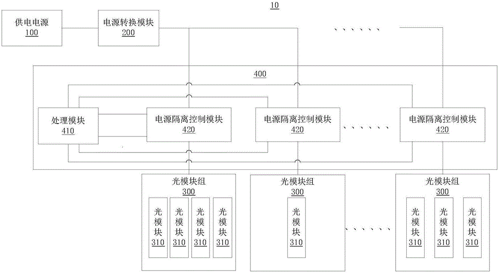
[0019] Such as figure 1 Shown is a schematic diagram of an optical module power supply system provided by a preferred embodiment of the present invention. The optical module power supply system 10 includes: a power supply 100 , a power conversi...


PUM


Abstract

The invention discloses a power supply device, an optical module power supply system and a power supply control method, and belongs to the field of power supply control of optical modules in communication devices. The power supply device includes a power supply isolation control module and a processing module, The processing module is used for obtaining a voltage value of input voltage of an optical module group, and when it is determined that the voltage value satisfies a first range, a control instruction is sent to the power supply isolation control module, so that a power supply conversion module and the optical module group are disconnected, and the power supply conversion module stops supplying power to the optical module group. Through the functions of the processing module and power supply isolation control module, when an abnormality of the input voltage input to the optical module group occurs, the power supply conversion module and the optical module group can be disconnected, thereby preventing a fault that occurs in the optical module group from influencing other optical modules that work normally, reducing the technical risk of optical module group power supply, and improving the reliability of an optical module power supply system.

Description

technical field [0001] The invention relates to the field of power supply control of optical modules in communication equipment, in particular to a power supply device, an optical module power supply system and a power supply control method. Background technique [0002] In order to meet the continuous large-scale demand for data and information traffic growth in the society, modern data communication equipment is also developing towards the technical direction of large-capacity single machine, high-speed service port and high-density service port, and in the connection of these service ports, optical fiber It is widely used for its high bandwidth, low attenuation, soft and light weight, convenient wiring in the equipment room, and good EMI / EMC performance. At the same time, for high-speed service ports of 40G and above, currently only optical fibers can be used for interconnection between devices. In addition, the high density of service ports of data communication equipmen...

Claims


Application Information

Patent Timeline
Patent Type & Authority Applications(China)
IPC IPC(8): H04B10/80H02J7/00
CPCH02J7/0029H02J7/0063H02J2207/10H04B10/808
Inventor 程鸿博
Owner MAIPU COMM TECH CO LTD
Why Eureka
Try Eureka