Method for manufacturing wound electronic component

A technology of electronic components and manufacturing methods, applied in coil manufacturing, inductance/transformer/magnet manufacturing, electrical components, etc., can solve the problem that the pulling force cannot be properly transmitted to the wire, and achieve the effect of suppressing disconnection

Active Publication Date: 2017-02-15
MURATA MFG CO LTD
View PDF5 Cites 5 Cited by
  • Summary
  • Abstract
  • Description
  • Claims
  • Application Information

AI Technical Summary

Problems solved by technology

As a result, the pulling force from the tensioner 502 cannot be appropriately transmitted to the wire downstream of the nozzle 503, and the wire 501 may be broken at the twisted portion of the wire 501 between the tensioner 502 and the nozzle 503. Wire

Method used


Image

  • Method for manufacturing wound electronic component
  • Method for manufacturing wound electronic component
  • Method for manufacturing wound electronic component

Examples


no. 3 example

[0071] (Refer to the third embodiment Figure 12 ~ Figure 17 )

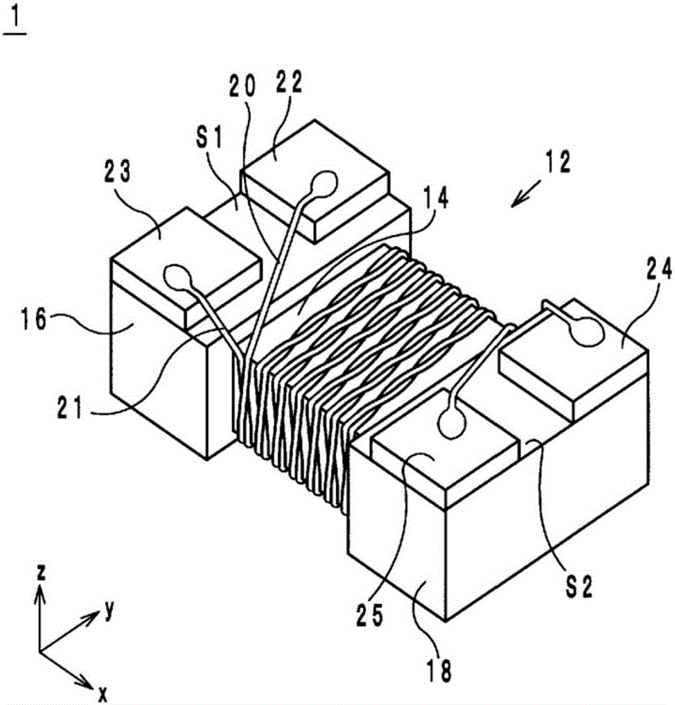
[0072] The manufacturing method of the coil-type electronic component of the third embodiment differs from the method of manufacturing the coil-type electronic component of the first embodiment in the method of fixing the coils 20 and 21 to the flange portion 16. The following is a specific description.

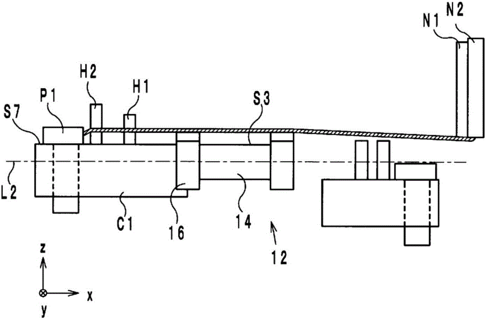
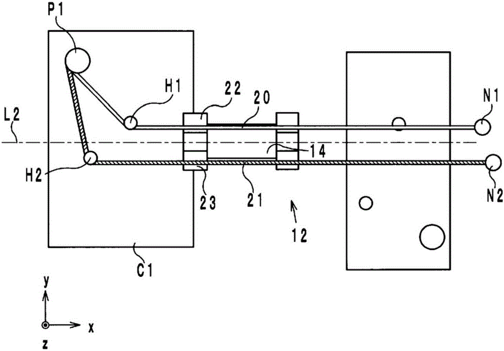
[0073] In the manufacturing method of the coil type electronic component of the third embodiment, after the coils 20 and 21 are caught on the hook pins H1 and H2 of the chuck C1, the chuck C1 is rotated by about 90°. As a result, the coil 20, 21 is Picture 12 as well as Figure 13 It is caught at the angle E1 formed by the surface S1 of the flange portion 16 and the surface S4 on the positive side of the x-axis direction of the flange portion 16 as shown.

[0074] Next, like Figure 14 as well as Figure 15 As shown, in the state where the windings 20 and 21 are caught at the angle E2 formed by the surface S5 on the...


PUM


Abstract

The purpose of this invention is to provide a method that is used to manufacture a wound electronic component using twisted wires and makes it possible, when twisting a plurality of winding wires together, to minimize breakage thereof. This method for manufacturing a wound electronic component (1) includes a preparation step in which a chuck (C1) is used to grip a core (12) that has a winding-core section (14) and flanges (16 and 18), a first step in which part of each of a number of winding wires (20, 21) supplied from respective nozzles (N1, N2) is affixed to one of the flanges (16), and a second step in which the chuck (C1) is rotated so as to twist the winding wires (20, 21).

Description

Technical field [0001] The present invention relates to a method of manufacturing a wire-wound electronic component, and more particularly to a method of manufacturing a wire-wound electronic component using twisted wires. Background technique [0002] As a conventional manufacturing method of a coil-type electronic component using twisted wires, a method of manufacturing a coil-type coil component described in Patent Document 1 is known. In such a method of manufacturing a wire-wound electronic component (hereinafter referred to as a method of manufacturing a conventional wire-wound electronic component), a plurality of wires are twisted and wound around the core portion. Here, the manufacturing device used in the conventional method of manufacturing wire-wound electronic components is Figure 19 As shown, it includes: a tensioner 502 for applying moderate tension to the wire 501 when winding the wire 501 from the upstream side of the supply wire 501 to the iron core 504 of the w...

Claims


Application Information

Patent Timeline
Patent Type & Authority Applications(China)
IPC IPC(8): H01F41/066H01F41/04
CPCH01F41/07H01F41/076H01F41/082B65H54/026
Inventor 山北高之
Owner MURATA MFG CO LTD
Why Eureka
Try Eureka