

Discharging processor for line electrode
A technology of electric discharge machine and wire electrode, applied to the field of wire electrode electric discharge machine, can solve problems such as reduced productivity, and achieve the effect of improving productivity
- Summary
- Abstract
- Description
- Claims
- Application Information
AI Technical Summary
Problems solved by technology
Method used
Image

Examples
Embodiment approach 1
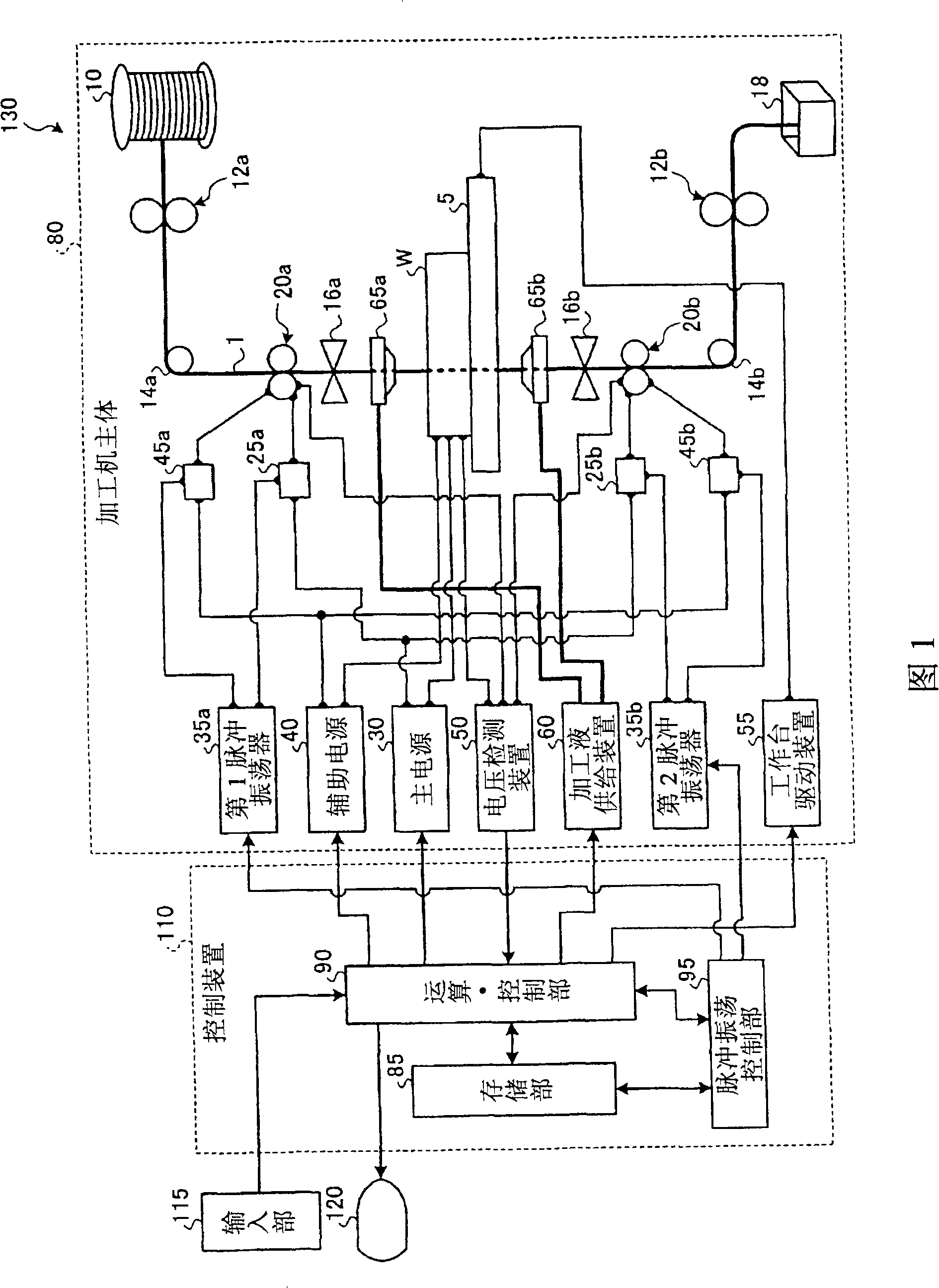
[0034]FIG. 1 is a configuration diagram schematically showing an example of a wire electric discharge machine according to the present invention. The wire electric discharge machine 130 shown in this figure has: a machine main body 80 which discharges the workpiece W into a predetermined shape by numerical control; Control; an input unit 115, which is connected to the control device 100 by wire or wirelessly, and inputs commands or data, etc., to the control device 100; and a display unit 120, which displays commands or data, etc. 80's operating status, etc.
[0035] The processing machine main body 80 applies a high-frequency pulse voltage to the wire electrode 1 moving in the thickness direction of the workpiece W, and processes the workpiece W by the electric discharge generated between the wire electrode 1 and the workpiece W. The workpiece W is placed on a table 5 movable on the X-Y plane (horizontal plane), and the wire electrode 1 moves across the thickness direction o...
Embodiment approach 2
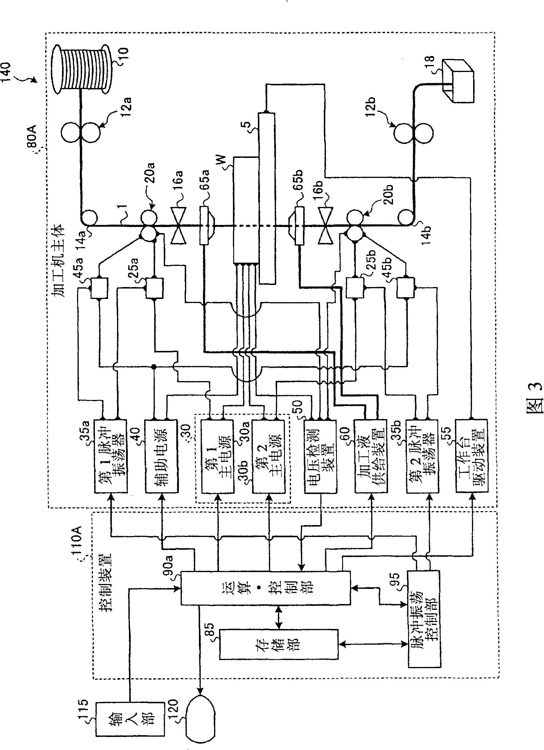
[0056] In the wire electric discharge machine of the present invention, in order to suppress overheating of the wire electrode at the central portion of the workpiece in the thickness direction, the main power supply may be divided into two parts, the first main power supply and the second main power supply.
[0057] FIG. 3 is a configuration diagram schematically showing an example of a wire electric discharge machining apparatus in which a main power source includes a first main power source and a second main power source. In the wire electric discharge machining apparatus 140 shown in the figure, the main power source 30 has a first main power source 30a and a second main power source 30b. The first main power supply 30a is connected to the upper power supply unit 20a via the first switching element unit 25a, and is also connected to the upper portion of the workpiece W in the thickness direction. Moreover, the 2nd main power supply 30b is connected to the lower side power ...
Embodiment approach 3
[0066] In a wire electric discharge machine, if the Z-axis height (relative height of the upper power feeding part) or the thickness of the workpiece changes, the distance from the discharge point to each power feeding part changes, and thus the distance from the upper power feeding part to The impedances of the feed circuit at the discharge point (hereinafter referred to as “upper feed circuit”) and the feed circuit leading to the discharge point via the lower feed portion (hereinafter referred to as “lower feed circuit”) vary in impedance. This impedance variation causes a difference in the magnitude of the discharge current in each power supply circuit, and in a power supply circuit with a large discharge current (a power supply circuit with a small impedance), wire electrode disconnection is likely to occur.
[0067] The wire electric discharge machine of the present invention can be configured to adjust the respective high-frequency pulse voltage supply conditions of the u...
PUM
 Abstract
Description
Claims
Application Information