Automatic wire bonder

An automatic wiring device and wire technology, applied in electric processing equipment, metal processing equipment, electrode manufacturing, etc., can solve the problems of easy disconnection, inability to set the thermal expansion of electrode wire through tension, and inability to obtain the straightness of electrode wire, etc.

Active Publication Date: 2013-10-09
MITSUBISHI ELECTRIC CORP
View PDF5 Cites 4 Cited by
  • Summary
  • Abstract
  • Description
  • Claims
  • Application Information

AI Technical Summary

Problems solved by technology

The strength of the electrode wire decreases with the temperature rise caused by heating, so it is easy to break due to external force such as tension
Especially when using a thin electrode wire less than or equal to φ0.1mm, it is easy to break the wire
In addition, even for relatively thick electrode wires of φ0.1 mm or more, wire breakage occurs when excessive tension is applied to the electrode wires during annealing.
[0008] On the other hand, when the tension is not applied to the electrode wire, the thermal expansion of the electrode wire due to heating cannot be wound by tension setting rollers, etc., and the electrode wire is heated in a state where the deflection remains, so there is a problem that the desired The problem of the linearity of the desired electrode wire

Method used


Image

  • Automatic wire bonder
  • Automatic wire bonder
  • Automatic wire bonder

Examples


Embodiment approach 1

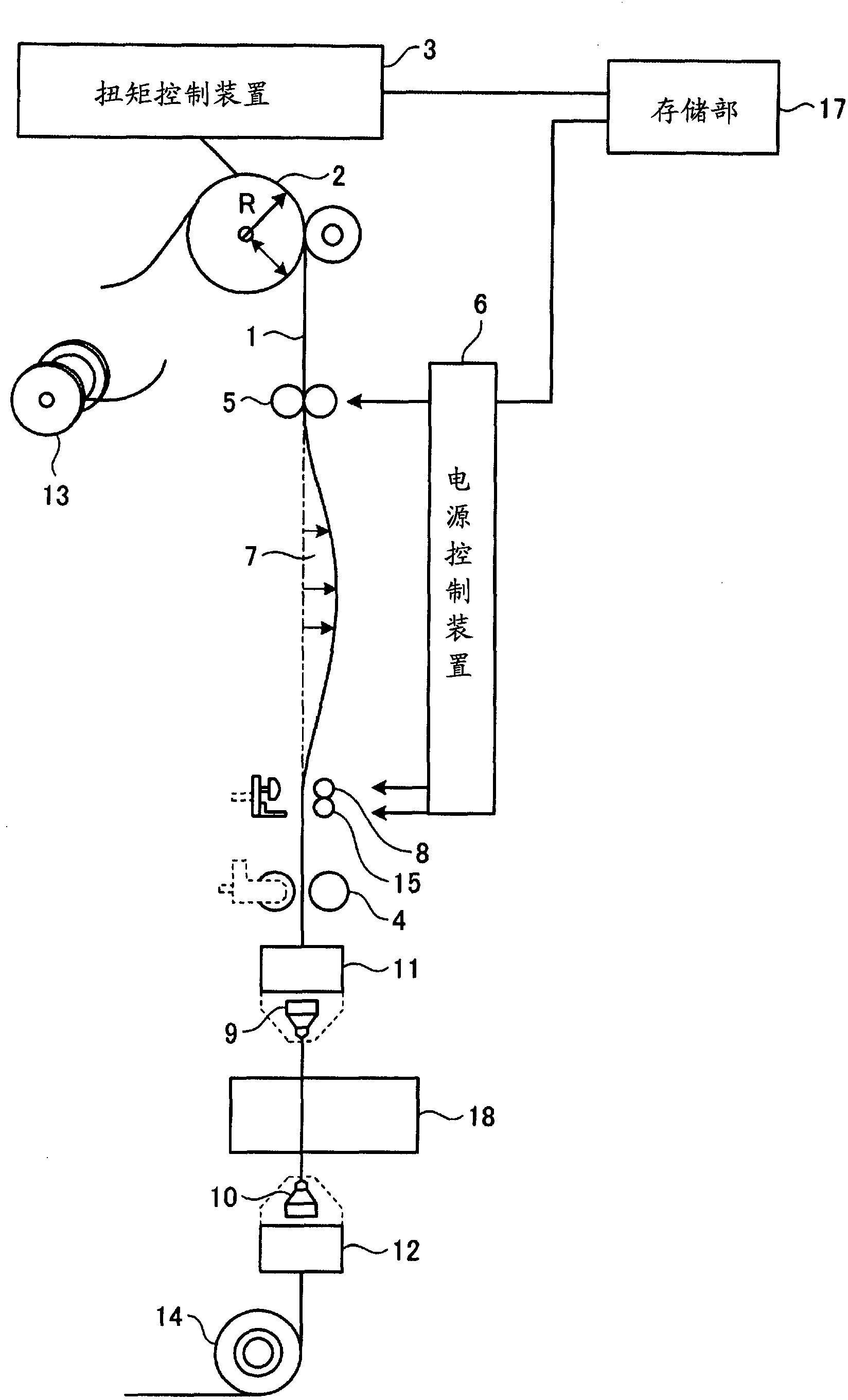
[0045] Next, Embodiment 1 of the present invention applied to the above-mentioned automatic wire splicing device will be described. That is, an automatic wire splicing device is described, which energizes the electrode wire 1 between the heating current electrode 5 and the GND electrode 15, and while applying tension to the electrode wire 1, the torque control device 3 controls the applied tension. The annealing treatment is performed in a state where the electrode wire 1 is hardly bent under tension.

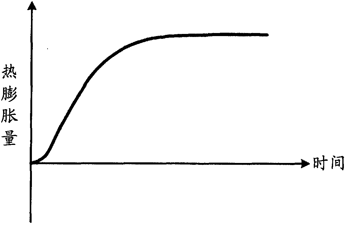
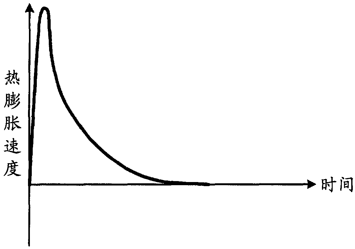
[0046] When current flows through the electrode wire 1 , the electrode wire 1 generates heat and its temperature rises due to the resistance of the electrode wire 1 , but heat transfer also occurs due to a temperature difference with the surroundings. When the electrode wire 1 is heated by passing current, the temperature of the electrode wire 1 rises sharply at first, and after a certain amount of time, the heat transfer also increases due to the temperature difference with th...

Embodiment approach 2

[0087] Figure 5 It is a figure which shows the flowchart for demonstrating the procedure of the process performed by the control apparatus of Embodiment 2. In Embodiment 1, it is determined from the initial torque command τ by the elapsed time since the current is applied to the electrode wire 1 . 1 The determination of the timing of the torque command from the torque control device 3 is reduced. On the other hand, in Embodiment 2, when the expansion amount of the electrode wire 1 reaches a predetermined amount of thermal expansion L 1 , the torque command is switched from the initial torque. In addition, the same reference numerals are assigned to the same configurations as those in the above-mentioned first embodiment, and detailed description thereof will be omitted.

[0088] When tension is continuously applied to the electrode wire 1 at the initial torque value, the tension setting roller 2 is rotated by the amount of thermal expansion of the wound electrode wire 1 . ...

Embodiment approach 3

[0095] Figure 6 It is a diagram showing a flowchart for explaining the procedure of processing executed by the control device according to the third embodiment. In Embodiment 1 and Embodiment 2, it is specified that the torque command from the torque control device 3 is changed from the initial torque value τ 1 Change to the final torque value τ 2 switching time t 2 , but otherwise, if in the elapsed time from the start of the switch (from t 1 The elapsed time from the start) reaches the set torque conversion time t 2 Before, the expansion of the electrode wire 1 reached the specified limit expansion L 2 , then transfer the torque command directly to τ 2 .

[0096] That is, by detecting the rotation amount of the tension setting roller 2 with an encoder of the tension setting roller 2 or the like, it is detected how much thermal expansion of the electrode wire 1 has occurred. When the elapsed time from the start of switching the torque command from the torque control d...


PUM


Abstract

An automatic wire connecting device includes a heating electrode that heats an electrode wire by applying a current to the electrode wire, a tension applying unit that applies a tension to the electrode wire to which the current is applied by the heating electrode, a tension control unit that controls the tension applied by the tension applying unit, and a power supply control unit that applies a heating current smaller than a preset annealing current to the electrode wire until a first set time elapses since the current starts to be applied and increases the current applied to the electrode wire to reach the annealing current during a second set time after the first set time elapses since the current starts to be applied.

Description

technical field [0001] The invention relates to a wire automatic wiring device of a wire discharge processing machine. Background technique [0002] There is a wire electric discharge machine that places an electrode wire composed of a metallic wire against a workpiece with a small gap therebetween, and cuts the workpiece by discharge energy. An automatic wire connection device that passes an electrode wire through a machining start hole of a workpiece before machining starts plays an important role in the technology for realizing the automation of wire electrical discharge machining. [0003] By using the wire automatic wiring device, it can be realized that the electrode wire is reconnected when the electrode wire is interrupted in the processing process, and the processing is restarted, and the processing can be carried out to other processing parts of the same processing material, or the newly provided workpiece after processing. Automatic insertion of electrode wires. ...

Claims


Application Information

Patent Timeline
Patent Type & Authority Applications(China)
IPC IPC(8): B23H7/10
CPCB23H7/08B23H7/104B23H7/10B23H7/102
Inventor 刘正勇长冈林太郎
Owner MITSUBISHI ELECTRIC CORP
Why Eureka
Try Eureka