Surface-mount base for electronic element

a technology of surface mounting and electronic elements, applied in the direction of impedence networks, fixed capacitors, device material selection, etc., can solve the problems of unstable positioning and difficult handling, and achieve the effect of facilitating the manufacture of surface mounting bases and increasing the accuracy of mounting positions of lead terminals

Inactive Publication Date: 2008-04-01
PANASONIC CORP
View PDF4 Cites 5 Cited by
  • Summary
  • Abstract
  • Description
  • Claims
  • Application Information

AI Technical Summary

Benefits of technology

[0009]Therefore, with the foregoing in mind, it is an object of the present invention to provide a surface-mount base, having a configuration in which when the surface-mount base is assembled, a lead terminal is mounted on a supporting member with a stable positioning. Disconnection of a lead terminal from a supporting member or a rattle in the supporting member can be suppressed, the manufacturing of the surface-mount base facilitated and an accuracy of a mounting position of the lead terminal increased.

Problems solved by technology

However, in order to make it easy for the lead terminal 23 to pass through the through hole 27, it is necessary for the through hole 27 to have a sufficient size, and therefore the lead portion 23b of the lead terminal 23 rattles in the through hole 27, thus making the positioning unstable, so that it is difficult to handle during the manufacturing process.

Method used


Image

  • Surface-mount base for electronic element
  • Surface-mount base for electronic element
  • Surface-mount base for electronic element

Examples


embodiment 1

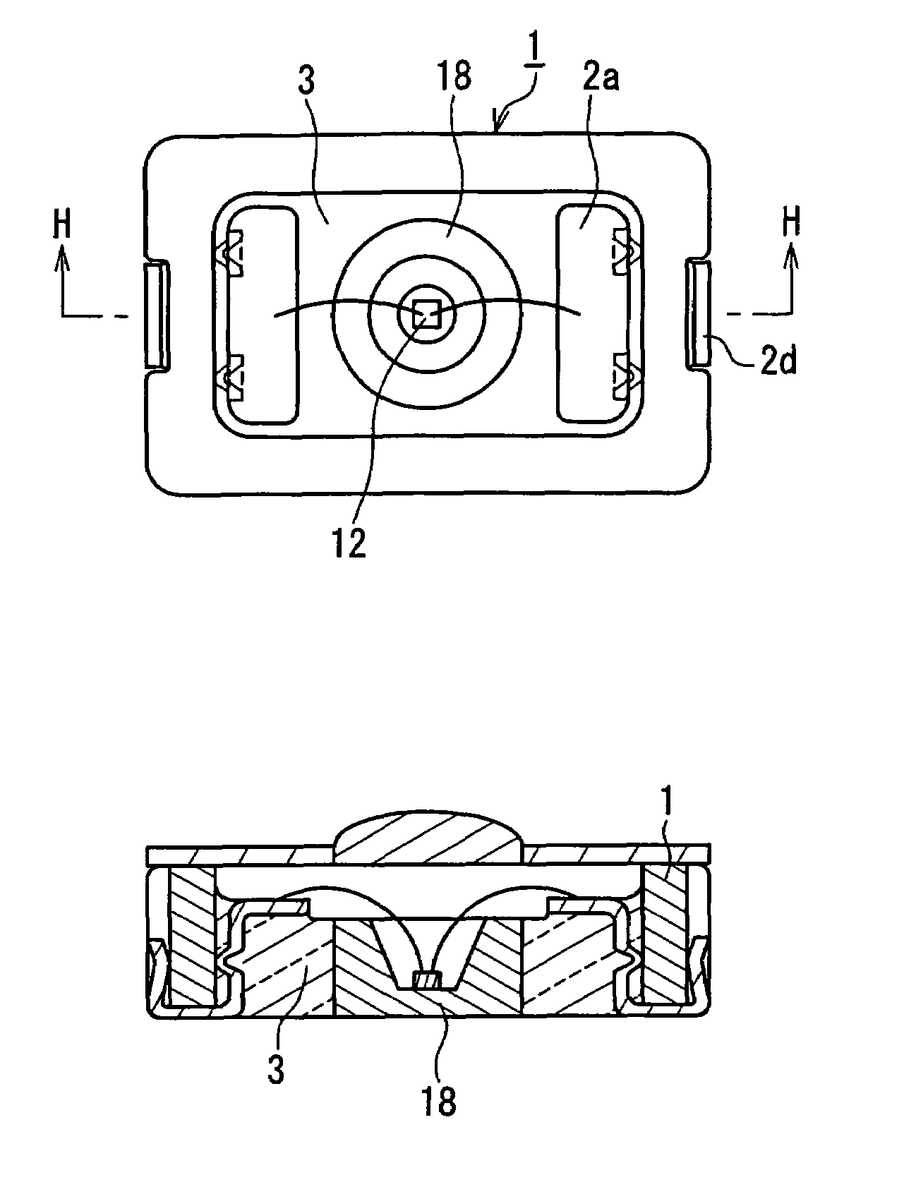
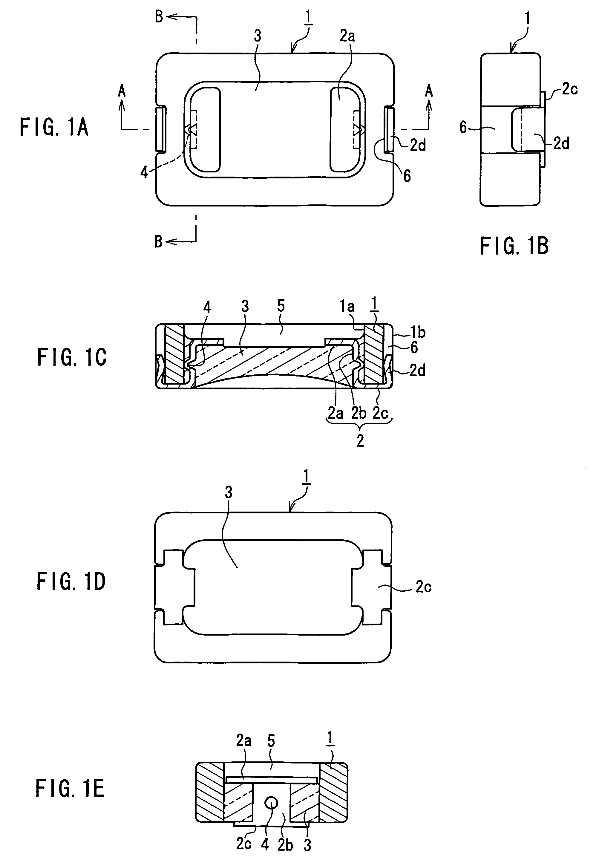
[0029]FIGS. 1A to 1E show a surface-mount base according to Embodiment 1. FIG. 1A is a plan view, FIG. 1B is a side view, FIG. 1C is a cross-sectional view taken along the line A-A of FIG. 1A, FIG. 1D is a rear-face view and FIG. 1E is a cross-sectional view taken along the line B-B of FIG. 1A. This surface-mount base includes: an insulative supporting frame 1, a pair of metal lead terminals 2 and a sealing glass 3.

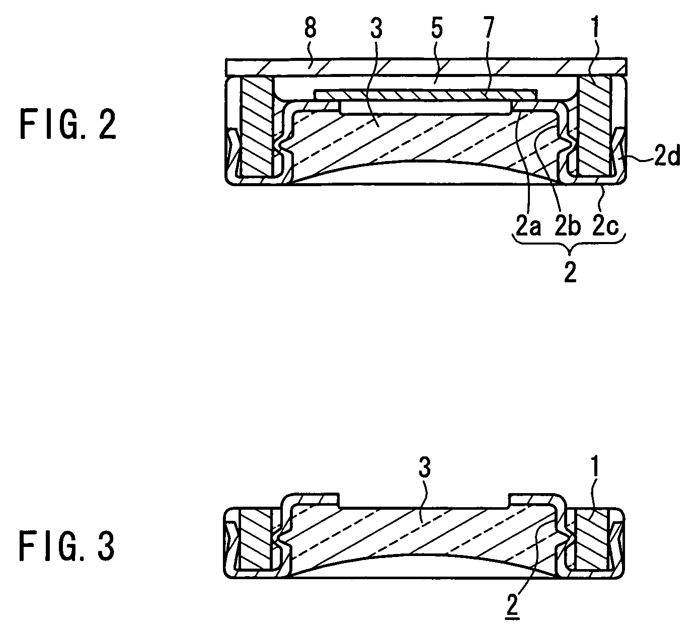
[0030]The supporting frame 1 is made of ceramic, for example, and has a frame form that is substantially rectangular. An inner cavity is defined by an inner face 1a of the supporting frame 1. Thus the frame form means a shape having an outer wall that defines a through hole. Each of the lead terminals 2 includes an element connecting terminal 2a, a lead portion 2b and a mounting terminal 2c. The lead terminal 2 is mounted on the supporting frame 1 with the lead portion 2b passing through the inner cavity of the supporting frame 1. The inner cavity in the supporting frame ...

embodiment 2

[0042]FIGS. 4A to 4E show a surface-mount base according to Embodiment 2. FIG. 4A is a plan view, FIG. 4B is a side view, FIG. 4C is a cross-sectional view taken along the line C-C of FIG. 4A, FIG. 4D is a rear-face view and FIG. 4E is a cross-sectional view taken along the line D-D of FIG. 4A. This surface-mount base is different from Embodiment 1 in the configuration of a lead terminal 9. The remaining configuration is the same as in Embodiment 1, and the same reference numerals are assigned to the same elements to avoid the duplication of explanations.

[0043]The lead terminal 9 includes an element connecting terminal 9a, a lead portion 9b, a mounting terminal 9c and an externally facing portion 9d. The portions other than the lead portion 9b are the same as those of the lead terminal 2 in Embodiment 1. The lead 9b forms a pair of branch lead portions 9b1 and 9b2, and an aperture is formed between the pair of branch lead portions 9b1 and 9b2. A protrusion 4 is formed at each of the...

embodiment 3

[0045]FIGS. 5A to 5D show a surface-mount base according to Embodiment 3. FIG. 5A is a plan view, FIG. 5B is a cross-sectional view taken along the line E-E of FIG. 5A, FIG. 5C is a front view and FIG. 5D is a rear-face view. This surface-mount base is different from Embodiment 1 in the shape of a lead terminal 10. The modification associated with this difference is made also to a supporting frame 1. The remaining configuration is the same as in Embodiment 1.

[0046]An element connecting terminal 10a of the lead terminal 10 traverses a supporting frame 1 and extends between two portions of an inner face 1a. A pair of lead portions 10b are formed so as to extend from both ends of the element connecting terminal 10a and each of the lead portions 10b faces the inner face 1a of the supporting frame 1. A pair of mounting terminals 10c are formed so as to extend from the pair of lead portions 10b, respectively. The pair of mounting terminals 10c each runs across a bottom face of the support...


PUM


Abstract

A surface-mount base for an electronic element includes: an insulative supporting member having a through hole; a plurality of lead terminals each having an element connecting terminal, a lead portion and a mounting terminal, the lead terminals being mounted to the supporting member with the lead portions passing through the through hole so that the element connecting terminals face a top face side of the supporting member and the mounting terminals face a bottom face side of the supporting member; and a sealing glass that is charged in the through hole of the supporting member for sealing the lead terminals in the through hole. The supporting member is composed of a supporting frame having an outer wall that defines the through hole, and at least one of the lead portion and the mounting terminal of each lead terminal has a shape and a dimension that cause a pressure against at least one of an inner face and an outer face of the outer wall, whereby the lead terminals are held on the supporting frame. The lead terminal is positioned on the supporting member while suppressing a disconnection or a rattle.

Description

FIELD OF THE INVENTION[0001]The present invention relates to a surface-mount base for electronic element that is used for supporting an electronic element such as a LED, a quartz resonator and so on, so as to facilitate the surface-mounting onto a circuit board. The present invention particularly relates to a surface-mount base that can be manufactured easily.BACKGROUND OF THE INVENTION[0002]A surface-mount type package with a quartz resonator mounted on a surface-mount base is compact and lightweight, and therefore is used often for a built-in purpose in, in particular, portable-type electronic equipment. Normally, in such a type of package, a quartz resonator is sealed after being mounted on a surface-mount base. For example, JP 2003-297453 A describes a surface-mount base with a consideration given to the compatibility with a circuit board on which the quartz resonator is to be mounted.[0003]FIG. 9 is a cross-sectional view of a package of a quartz resonator using a surface-mount...

Claims


Application Information

Patent Timeline
Patent Type & Authority Patents(United States)
IPC IPC(8): H01R12/04H05K1/11H01L41/09H01G4/00H01L23/04H01L41/18H01R12/00H03H9/05H03H9/10H05K1/14H05K3/32
CPCH01L33/483H01L33/62H03H9/1014H03H9/0514H01L33/54H01L33/58H01L2224/48091H01L2924/00014
Inventor NAKAI, HIROSHI
Owner PANASONIC CORP
Why Eureka
Try Eureka