High mixing power blending device capable of separately adding solid and liquid

A mixing device and mixing force technology, applied in the field of mixing machinery, can solve the problems of product quality not meeting the use standard, insufficient material mixing, slow mixing speed, etc., and achieve the effects of easy upper and lower mixing, easy mixing, and energy saving.

Inactive Publication Date: 2017-02-22
ZHENGZHOU YOUAI NETWORK TECH CO LTD
8 Cites 12 Cited by

AI-Extracted Technical Summary

Problems solved by technology

[0002] At present, with the development of science and technology, mixing tanks are widely used in the food production industry in pharmaceutical and chemical industries. Usually, mixing tanks are used to accelerate the reaction of materials in the kettle and to make the materials homogeneous. In order to achieve the purpose of stirring, some chemical raw materials It is often necessary to add other raw materials in the process to fully mix the chemical raw...

Abstract

The invention provides a high mixing power blending device capable of separately adding solid and liquid. The high mixing power blending device comprises a mixing tank, an upper cover and a driving box, wherein a top opening of the mixing tank is provided with the upper cover; the upper cover is provided with a solid charging device and a liquid charging device; the solid charging device consists of a smashing tank, a smashing motor, a smashing spindle and smashing blades; the liquid charging device consists of a transmission box, a servo motor and a rotary sprinkling disc; a third gear, a fourth gear and a fifth gear are arranged in the transmission box; the third gear and the fourth gear are mutually meshed, and the third gear and a second stirring shaft in a second stirring device are fixedly connected; the fifth gear and the fourth gear are mutually meshed, and the fifth gear and a first stirring shaft in a first stirring device are fixedly connected. Through the lifting and the lowering of a lifting plate, materials can be vertically mixed, and the materials on the bottom of the mixing tank are stirred and mixed by the first stirring device and the second stirring device.

Application Domain

Technology Topic

Image

  • High mixing power blending device capable of separately adding solid and liquid
  • High mixing power blending device capable of separately adding solid and liquid
  • High mixing power blending device capable of separately adding solid and liquid

Examples

  • Experimental program(1)

Example Embodiment

[0017] The technical solution of this patent will be described in further detail below in conjunction with specific embodiments.
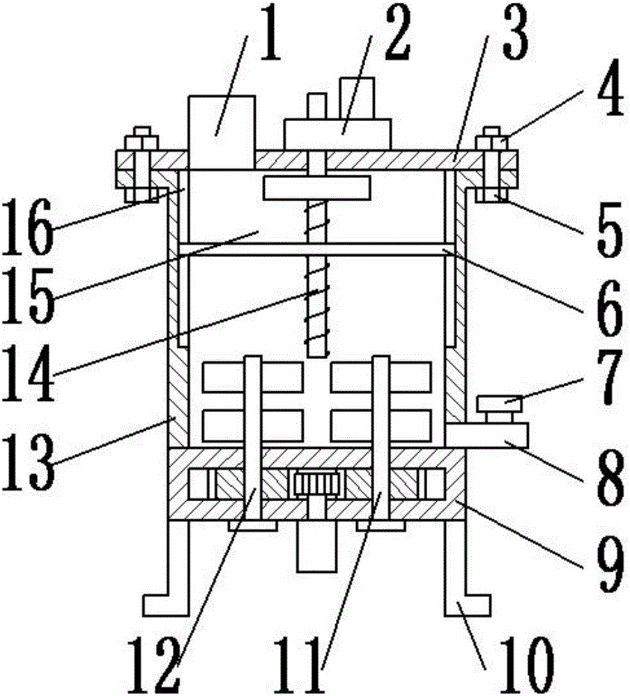
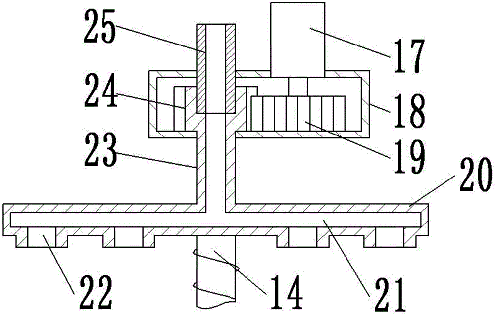
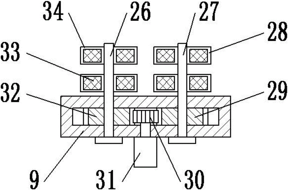
[0018] See Figure 1-5 , A high-stirring mixing device for separate solid and liquid addition, comprising a mixing tank 13, an upper cover 3 and a drive box 9; the mixing tank 3 is arranged in a cylindrical body with a mixing cavity 15 inside; the top opening of the mixing tank 3 An upper cover 3 is provided; the upper cover 3 is fixedly connected to the mixing tank 3 by mutual screwing of bolts 5 and nuts 4; the upper cover 3 is provided with a solid feeding device 1 and a liquid feeding device 2; the solid feeding device 1 Composed of a crushing tank 39, a crushing motor 38, a crushing shaft 42 and a crushing blade 40; the bottom of the high-speed crushing tank 39 is provided with a filter 41, and the inside is fixedly connected to the crushing motor 38 through a fixed rod 38; the main shaft of the crushing motor 38 is connected to The pulverizing shaft 42 is fixedly connected; the pulverizing shaft 42 is provided with a pulverizing blade 40; the pulverizing blade 40 is provided with three layers on the pulverizing shaft 42, each layer is provided with two pieces; the solid feeding device 1 is set up to be used for matching The block of solid materials is crushed to facilitate full mixing with liquid materials and speed up work efficiency; the liquid feeding device 2 is composed of a transmission box 18, a servo motor 17 and a rotating spray plate 20; the transmission box 18 is provided with a first A gear 19 and a second gear 24; the first gear 19 is fixedly connected to the main shaft of the servo motor 17; the servo motor 17 is fixed on the upper surface of the transmission box 18 for providing rotational power; the second gear 24 is connected to The first gears 19 mesh with each other, and the top of the second gear 24 is movably connected with the liquid inlet tube 25, and the bottom is fixedly connected with one end of the connecting tube 23; the liquid inlet tube 25 is fixedly connected with the transmission box 18 for introducing liquid materials; The other end of the connecting pipe 23 is fixedly connected with the rotating spray plate 20; the rotating spray plate 20 is arranged in a disc shape with a number of nozzles 22 evenly arranged on the lower surface; the second gear 24, the connecting pipe 23 and the rotating spray plate There is a flow channel 21 inside the shower tray 20; the liquid feeding device 2 is arranged to spray liquid materials through the rotating rotating spray tray 20, which is convenient to expand the contact area of ​​the liquid material and the solid material, and facilitates rapid mixing; the rotating spray tray The middle part of the lower surface of 20 is fixedly connected with the top of the threaded screw 14; the threaded screw 14 is arranged in the mixing cavity 15, and the threaded screw 14 is provided with a lifting plate 6; the lifting plate 6 is arranged in a circular shape, and the middle part is arranged There are threaded holes 36; a number of guide holes 37 are evenly distributed around the threaded holes 36; two ends of the lifting plate 6 are provided with sliders 35; the sliders 35 are provided on the slideways 16 provided on the side wall of the mixing tank 13 Middle; Through the forward and reverse rotation of the threaded screw 14, the lifting plate 6 is raised and lowered, which is convenient for mixing the materials up and down; the bottom side wall of the mixing tank 13 is provided with a discharge pipe 8; the discharge pipe 8 is provided There is a discharge valve 7; the drive box 9 is arranged at the bottom of the mixing tank 13, and a third gear 29, a fourth gear 30 and a fifth gear 32 are arranged inside; the third gear 29 and the fourth gear 30 mesh with each other, And the third gear 29 is fixedly connected to the second stirring shaft 27 in the second stirring device 11; the second stirring device 11 is composed of the second stirring shaft 27 and the second stirring blade 28; The two stirring blades 28 are provided with two layers on the second stirring shaft 27; the fourth gear 30 is fixedly connected to the main shaft of the driving motor 31; the driving motor 31 is fixed on the lower surface of the driving box 9 for providing rotational power; The fifth gear 32 and the fourth gear 30 mesh with each other, and the fifth gear 32 is fixedly connected to the first stirring shaft 26 in the first stirring device 12; the first stirring device 12 is composed of the first stirring shaft 26 and the first stirring shaft 26. It consists of a stirring blade 34; the first stirring blade 34 is provided with two layers on the first stirring shaft 26; the surface of the first stirring blade 34 and the second stirring blade 28 is provided with an electric heating net 33 for heating the material, It is convenient to speed up the mixing; the setting of the drive box 9 is used to drive the rotation of the first stirring device 12 and the second stirring device 11, stirring and mixing the materials at the bottom of the mixing tank 13, and it is driven by only one motor, which is convenient for energy saving; A bracket 10 is provided on the bottom surface of the box 9.
[0019] The preferred embodiments of this patent are described in detail above, but this patent is not limited to the above embodiments. It can also be made without departing from the purpose of this patent within the scope of knowledge possessed by those of ordinary skill in the art. Various changes.

PUM

no PUM

Description & Claims & Application Information

We can also present the details of the Description, Claims and Application information to help users get a comprehensive understanding of the technical details of the patent, such as background art, summary of invention, brief description of drawings, description of embodiments, and other original content. On the other hand, users can also determine the specific scope of protection of the technology through the list of claims; as well as understand the changes in the life cycle of the technology with the presentation of the patent timeline. Login to view more.

Similar technology patents

Classification and recommendation of technical efficacy words

  • Increase contact area
  • Improve work efficiency

Improved novel energy automobile charging device

Owner:XIAMEN YINLV JIEYUAN ENVIRONMENTAL PROTECTION TECH CO LTD

Full-automatic water-drill grinding and polishing machine

InactiveCN101758433AImprove work efficiencyFixture positioning is accurateEdge grinding machinesManipulatorEngineering
Owner:瑞安市天成包装机械有限公司
Why Eureka
Try Eureka