High-efficiency automatic cleaning device of numerical control machine tool

An automatic cleaning and CNC machine tool technology, which is applied to metal processing machinery parts, maintenance and safety accessories, metal processing equipment, etc., can solve problems affecting production efficiency, economic loss, and production accuracy, and achieve convenient and ingenious use and cleaning efficiency High, simple structure effect

Inactive Publication Date: 2017-02-22
合肥齐飞信息技术有限公司
View PDF7 Cites 4 Cited by
  • Summary
  • Abstract
  • Description
  • Claims
  • Application Information

AI Technical Summary

Problems solved by technology

[0002] CNC lathe is a high-precision, high-efficiency automatic machine tool. Equipped with multi-station turret or power turret, the machine tool has a wide range of processing performance, and can process straight cylinders, oblique cylinders, arcs and various threads. , slots, worms and other complex workpieces, with linear interpolation, circular interpolation and various compensation functions, and played a good economic effect in the mass production of complex parts, due to the working environment, factory management system and human factors, It is easy to cause the factory to fail to clean and maintain the equipment normally, which will lead to changes in the accuracy of the machine tool and affect the production accuracy. After the conveyor belt in the CNC machine tool has been used for a long time, a large amount of debris and impurities will adhere to the surface of the conveyor belt, and the staff often Neglect to clean it, and at the same time, it is difficult to clean up the sundries after a long time, which also affects the production efficiency and will cause certain economic losses

Method used


Image

  • High-efficiency automatic cleaning device of numerical control machine tool
  • High-efficiency automatic cleaning device of numerical control machine tool
  • High-efficiency automatic cleaning device of numerical control machine tool

Examples


Embodiment Construction

[0016] The following will clearly and completely describe the technical solutions in the embodiments of the present invention with reference to the accompanying drawings in the embodiments of the present invention. Obviously, the described embodiments are only some, not all, embodiments of the present invention.

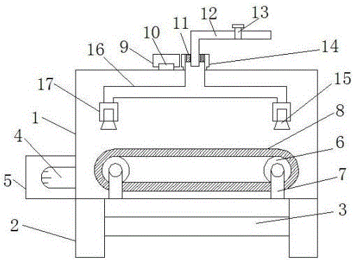
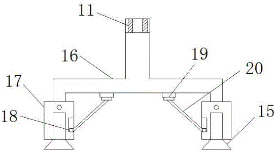
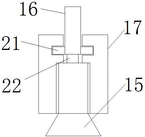
[0017] refer to Figure 1-3 , a high-efficiency automatic cleaning device for a CNC machine tool, comprising a body shell 1, symmetrical support frames 2 are provided on both sides of the lower end of the body shell 1, a horizontal frame 3 is provided between the two support frames 2, and a motor is provided on one side of the body shell 1. 4. There are two symmetrical support columns 7 on the bottom of the inner side of the body shell 1, and the two support columns 7 are respectively provided with a rotating shaft 6, and a conveyor belt 8 is provided between the two rotating shafts 6, and a notch is provided in the middle of the upper end of the body shell 1. A wate...


PUM


Abstract

The invention discloses a high-efficiency automatic cleaning device of a numerical control machine tool. The device comprises a machine body shell; symmetric support frames are arranged on two sides of the lower end of the machine body shell; a transverse frame is arranged between the two support frames; a conveying belt is arranged between two rotating shafts; two water separation pipes perpendicular to a water spraying pipe are arranged at an extension end of the water spraying pipe; connecting sleeves are arranged at one ends of the two pipes; rotating blocks are respectively arranged on two sides of extension ends of the two pipes; nozzles are arranged at one ends, near the rotating blocks, of the two pipes; second grooves are symmetrically formed in one sides of the two connecting sleeves; slide blocks are arranged in the two second grooves; extension rods are fixedly connected to the two slide blocks; a bearing is sleeved in the pipe wall of one end, near a notch, of the water spraying pipe; and a water inlet pipe is inserted in the bearing. The device is simple in structure, easy to operate and high in cleaning efficiency, realizes multi-angle and multi-direction cleaning, is convenient and skillful in use, and is suitable for wide popularization.

Description

technical field [0001] The invention relates to the technical field of machine tool equipment, in particular to a high-efficiency automatic cleaning device for a numerically controlled machine tool. Background technique [0002] CNC lathe is a high-precision, high-efficiency automatic machine tool. Equipped with multi-station turret or power turret, the machine tool has a wide range of processing performance, and can process straight cylinders, oblique cylinders, arcs and various threads. , slots, worms and other complex workpieces, with linear interpolation, circular interpolation and various compensation functions, and played a good economic effect in the mass production of complex parts, due to the working environment, factory management system and human factors, It is easy to cause the factory to fail to clean and maintain the equipment normally, which will lead to changes in the accuracy of the machine tool and affect the production accuracy. After the conveyor belt in ...

Claims


Application Information

Patent Timeline
Patent Type & Authority Applications(China)
IPC IPC(8): B23Q11/00
CPCB23Q11/00
Inventor 吴彩云
Owner 合肥齐飞信息技术有限公司
Why Eureka
Try Eureka