Numerical control abrasive belt grinding tooling for intake and exhaust edges of precise forged stator blade of aircraft engine

An aero-engine, intake and exhaust edge technology, which is used in abrasive belt grinders, workpiece supports for grinding, machine tools suitable for grinding workpiece edges, etc. The length of the gas edge grinding and the unreasonable structural design of the positioning block can achieve the effect of compact structure, reducing the number of fixtures and reducing the processing cost.

Active Publication Date: 2017-02-22
AECC AVIATION POWER CO LTD
View PDF5 Cites 7 Cited by
  • Summary
  • Abstract
  • Description
  • Claims
  • Application Information

AI Technical Summary

Problems solved by technology

The currently used tooling places the double floating V-shaped in the positioning block. The structural design of the positioning block is unreasonable, which leads to interference between the machining process and the grinding head of the machine tool, affects the grinding length of the intake and exhaust edges, and causes blade end bends and curvature transitions. It cannot be processed normally, which reduces the processing quality of the product; at the same time, the fixtures of blades of all levels cannot be used in common, and the number of fixtures is large, which increases the manufacturing cost and the complexity of processing operations.

Method used


Image

  • Numerical control abrasive belt grinding tooling for intake and exhaust edges of precise forged stator blade of aircraft engine
  • Numerical control abrasive belt grinding tooling for intake and exhaust edges of precise forged stator blade of aircraft engine
  • Numerical control abrasive belt grinding tooling for intake and exhaust edges of precise forged stator blade of aircraft engine

Examples


Embodiment Construction

[0038] The present invention will be further described below in conjunction with accompanying drawing,

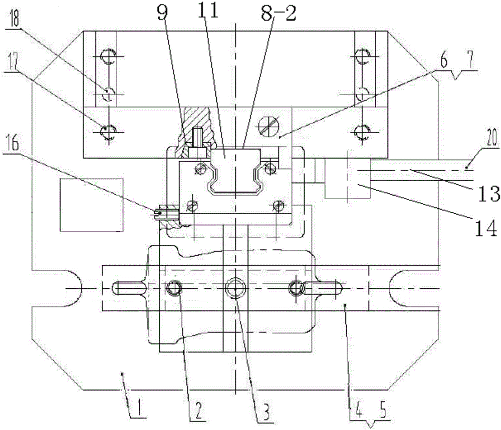
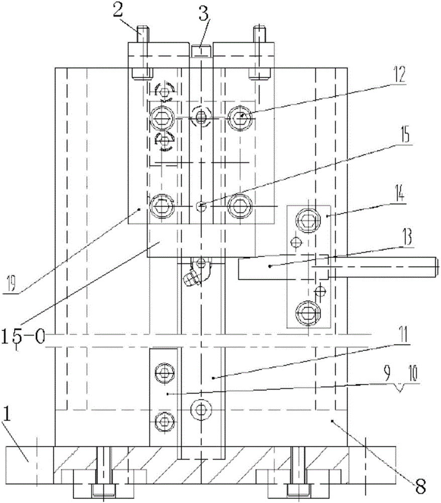
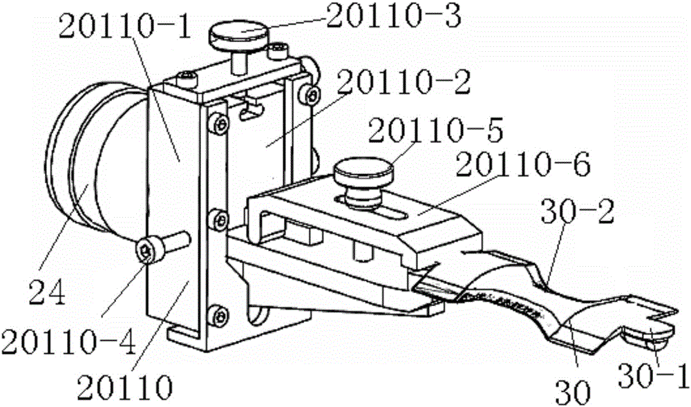
[0039] Such as figure 1 yes Figure 8 As shown, the aeroengine precision forging stator blade inlet and exhaust edge numerical control abrasive belt grinding tooling of the present invention includes a clamp 20110 for clamping the process boss 30-1 at both ends of the blade 30, and is used for adjusting the blade surface 30-1. 2 Positioning the profile positioning block 20109 and the clamp base 5200, the profile positioning block 20109 is arranged on the clamp base 5200;

[0040]The fixture base 5200 includes a base plate 1, a support 8 is provided on the base plate 1, a vertical linear guide rail 11 is provided on the support 8, a groove 8-2 is opened on the support 8, and the linear guide rail 11 is arranged in the groove 8-2. There is also a pressure block 9 in the groove 8-2, one side of the linear guide rail 11 is close to one side of the groove 8-2, and the pressure...


PUM


Abstract

The invention relates to a numerical control abrasive belt grinding tooling for intake and exhaust edges of a precise forged stator blade of an aircraft engine. The numerical control abrasive belt grinding tooling comprises fixtures used for clamping technological bosses at the two ends of the blade, a molded surface locating block used for locating a blade molded surface, and a fixture base, wherein the molded surface locating block is arranged on the fixture base; the fixture base comprises a bottom plate; a bracket is arranged on the bottom plate; a vertical linear guide rail is arranged on the bracket; a movable sliding block which can move up and down along the linear guide rail is arranged on the linear guide rail; a support is fixed to the movable sliding block; the molded surface locating block is fixed to the upper end of the support; a limiting device is further arranged on the bracket; the limiting device is used for fixing the support at a preset height; locating pins are arranged at the upper end of the molded surface locating block; and during locating, second locating pins are in contact with the blade molded surface of the blade, and first locating pins are in contact with the side surfaces of the blade technological bosses of the blade. According to the numerical control abrasive belt grinding tooling, the tooling structure adopts split design, the molded surface and a locating point are separated, and parts are clamped at one time.

Description

[0001] 【Technical field】 [0002] The invention is a tooling applied to the CNC abrasive belt grinding process of the air intake and exhaust edges of precision forging stator blades of aero-engine compressors, specifically the CNC abrasive belt grinding tooling of the air intake and exhaust edges of precise forging stator blades of aero-engines. Under the requirements of precision and rigidity, the general-purpose tooling with exquisite structure, convenient operation and no interference in processing is designed. [0003] 【Background technique】 [0004] With the development of manufacturing technology, CNC abrasive belt grinding is used to replace the traditional manual polishing for the processing of the inlet and exhaust edges of aeroengine compressor blades. The currently used tooling places the double floating V-shaped in the positioning block. The structural design of the positioning block is unreasonable, which leads to interference between the machining process and the ...

Claims


Application Information

Patent Timeline
Patent Type & Authority Applications(China)
IPC IPC(8): B24B9/04B24B21/16B24B41/06
CPCB24B9/04B24B21/165B24B41/068
Inventor 李飞魏王涛江波张义德许立君师胜男豆雷红杨柳川
Owner AECC AVIATION POWER CO LTD
Why Eureka
Try Eureka