Blow-drying device used for wood-plastic floors

A technology for wood-plastic flooring and bottom boards, applied in applications, household appliances, household components, etc., can solve the problems of low drying operation efficiency, unsuitable wood-plastic flooring, residual moisture, etc., and achieve high-efficiency and energy-saving blow-drying effects with simple structure Effective and high energy utilization

Active Publication Date: 2017-02-22
浙江天博生物新材料股份有限公司
View PDF7 Cites 0 Cited by
  • Summary
  • Abstract
  • Description
  • Claims
  • Application Information

AI Technical Summary

Problems solved by technology

[0003] Most of the blow-drying devices in the prior art are in the way that the fan rotates continuously after power-on and blows up and down. There are two defects in this way: first, the fan is in the normal open state, and the interval between the actions of the wood-plastic floor is placed in sequence. In the gap, there is a waste of electric energy due to ineffective blow-drying. Second, the way of blowing up and down is not suitable for wood-plastic flooring with openings in the middle. There are problems of incomplete drying and residual moisture in the middle opening. Therefore, the existing The wood-plastic floor manufacturing industry is in urgent need of an efficient and applicable drying device
[0005] The utility model has the problem of low drying operation efficiency

Method used


Image

  • Blow-drying device used for wood-plastic floors
  • Blow-drying device used for wood-plastic floors
  • Blow-drying device used for wood-plastic floors

Examples


Embodiment Construction

[0022] The following descriptions are only preferred embodiments of the present invention, and do not limit the scope of the present invention.

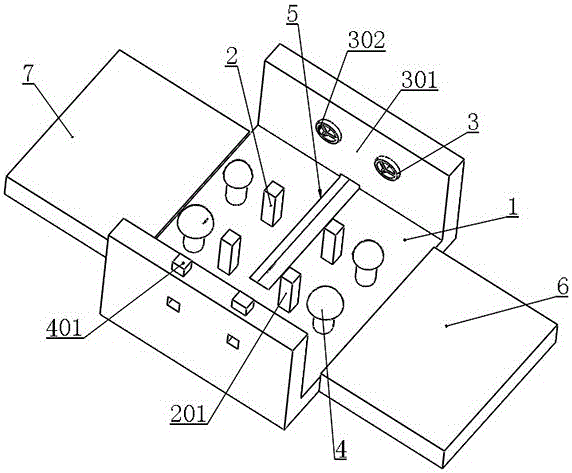
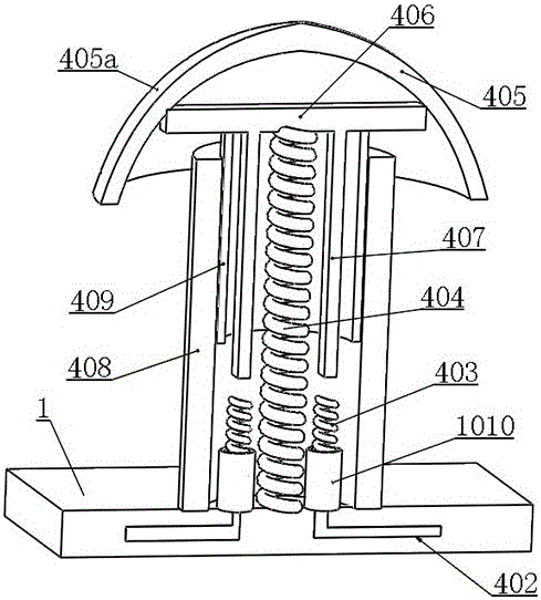
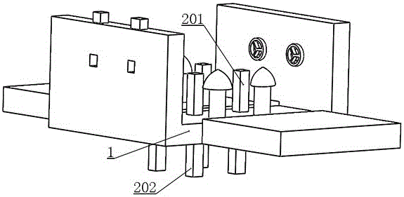
[0023] Example: as attached figure 1 , 2 , 3 and attached Figure 4 As shown, a drying device for wood-plastic flooring includes a drying device bottom plate 1, a support unit 2 arranged on the drying device bottom plate 1 for supporting the wood-plastic floor and the drying device bottom plate 1 , the drying fan unit 3 arranged on the base plate 1 of the drying device and the fan power supply unit 4 for triggering the drying fan unit 3 to carry out the drying action, the drying fan unit 3 is arranged on the support Both sides of unit 2.

[0024] In this embodiment, the wood-plastic floor is placed on the support unit 2, and the fan energization unit 4 is pressed down, so that the fan energization unit 4 is turned on, and the drying fan unit 3 is dried. action, wherein the blowing direction of the drying fan unit 3 is consistent ...


PUM


Abstract

The invention belongs to the technical field of manufacturing and processing equipment of wood-plastic floors, and particularly relates to a blow-drying device used for the wood-plastic floors. The blow-drying device used for the wood-plastic floors comprises a blow-drying device base board, supporting units, blow-drying fan units and fan power-on units. The supporting units are arranged on the blow-drying device base board and used for supporting the wood-plastic floors and the blow-drying device base board, the blow-drying fan units are arranged on the blow-drying device base board, and the fan power-on units are used for triggering the blow-drying fan units to conduct blow-drying action. The blow-drying fan units are arranged on the two sides of the supporting units. According to the blow-drying device used for the wood-plastic floors, blow-drying is triggered after the wood-plastic floors are placed into the device, the blow-drying fan units are located on the two sides of the wood-plastic floors, and thus the blow-drying way capable of achieving a high electric energy utilization ratio and a good blow-drying effect is achieved. The blow-drying device used for the wood-plastic floors has the advantages of being simple and effective in structure, good in blow-drying effect, efficient and capable of saving energy.

Description

technical field [0001] The invention belongs to the technical field of manufacturing and processing equipment for wood-plastic flooring, and in particular relates to a drying device for wood-plastic flooring. Background technique [0002] Wood-plastic flooring is a green and environmentally friendly floor made of wood (wood cellulose, plant cellulose), thermoplastic polymer materials (plastics) and processing aids, etc., which are mixed evenly and then heated and extruded by mold equipment. Type floor, both the performance and characteristics of wood and plastic. In the manufacturing process of wood-plastic flooring, blow-drying operation is essential, and only the wood-plastic floor after drying can be stored in the next step. [0003] Most of the blow-drying devices in the prior art are in the way that the fan rotates continuously after power-on and blows up and down. There are two defects in this way: first, the fan is in the normal open state, and the interval between t...

Claims


Application Information

Patent Timeline
IPC IPC(8): B29C37/00B27N3/18B29L31/10B29L7/00
CPCB27N3/18B29C37/0092B29L2007/002B29L2031/10
Inventor 吴晓雷侯孝刚陈建伟
Owner 浙江天博生物新材料股份有限公司
Why Eureka
Try Eureka