Rubber elastic joint injection mold

An elastic node and injection mold technology, applied in the field of molds, can solve the problem of difficulty in removing rubber elastic nodes, and achieve the effect of uniform force

Active Publication Date: 2017-02-22
CRRC QINGDAO SIFANG ROLLING STOCK RES INST
View PDF2 Cites 1 Cited by
  • Summary
  • Abstract
  • Description
  • Claims
  • Application Information

AI Technical Summary

Problems solved by technology

[0005] Aiming at the technical problem that it is difficult to remove the vulcanized rubber elastic nodes from the mold, the present invention proposes a rubber elastic node that efficiently removes the vulcanized rubber elastic nodes from the mold, and at the same time, can meet the mass production requirements of the rubber elastic nodes injection mold

Method used


Image

  • Rubber elastic joint injection mold
  • Rubber elastic joint injection mold
  • Rubber elastic joint injection mold

Examples


Embodiment Construction

[0031] In the following, the present invention will be specifically described through exemplary embodiments. It should be understood, however, that elements, structures and characteristics of one embodiment may be beneficially incorporated in other embodiments without further recitation.

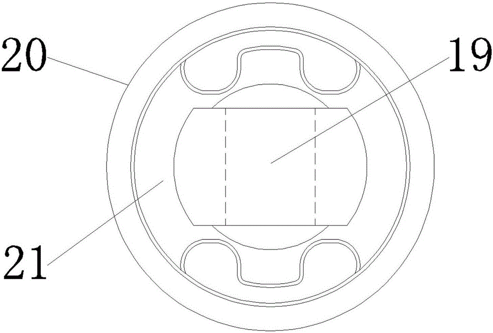
[0032] In the description of the present invention, it should be noted that the orientation or positional relationship indicated by the terms "upper", "lower" and so on is based on the attached image 3 The positional relationship shown is only for the convenience of describing the present invention and simplifying the description, but does not indicate or imply that the referred device or element must have a specific orientation, be constructed and operated in a specific orientation, and therefore cannot be construed as limiting the present invention . In addition, the terms "first", "second", and "third" are used for descriptive purposes only, and should not be construed as indicating or ...


PUM


Abstract

The invention provides a rubber elastic joint injection mold which comprises an upper mold body, a lower mold body and a middle mold body. The upper mold body comprises a top plate located at the top of the upper mold body, an upper core mold fixing plate arranged on the lower portion of the top plate, upper core molds fixedly arranged on the upper core mold fixing plate, an upper push plate arranged on the lower portion of the upper core mold fixing plate and a limit piece capable of limiting the upper core mold fixing plate to move vertically. The lower mold body comprises a base plate located at the bottom and lower core molds fixedly arranged on the base plate. The middle mold body comprises a lower push plate arranged above the base plate, clamping blocks which are arranged between the adjacent lower core molds correspondingly and are fixedly arranged at the top of the lower push plate, and slide blocks capable of horizontally sliding along the top of the lower push plate. By adoption of the rubber elastic joint injection mold, vulcanized rubber elastic joints can be effectively taken out of the mold, and meanwhile, requirements of large-batch production of the rubber elastic joints can be met.

Description

technical field [0001] The invention belongs to the technical field of molds, in particular to a rubber elastic joint injection mold. Background technique [0002] Rubber elastic joints are widely used in rail vehicle bogies to play the functions of vibration reduction and vibration isolation, which play an important role in the safety, comfort and stability of vehicle operation. Referring to Figure 1(a), Figure 1(b) and Figure 1(c), the rubber elastic node is composed of a mandrel 19, a jacket 20 and a rubber 21, wherein the mandrel 19, the jacket 20 and the rubber 21 are bonded by thermal vulcanization Vulcanized together, the rubber type 21 faces are separated with two through holes. [0003] The characteristics of the rubber elastic nodes shown in Fig. 1(a), Fig. 1(b) and Fig. 1(c) are: (1) Since the transition zone between the mandrel 19 and the rubber 21 at the end is straight, therefore, in the high-pressure injection During the sizing process, the sizing material w...

Claims


Application Information

Patent Timeline
Patent Type & Authority Applications(China)
IPC IPC(8): B29C45/32B29C45/40
CPCB29C45/32B29C45/40
Inventor 刘兆栋刘志坡于磊宋红光
Owner CRRC QINGDAO SIFANG ROLLING STOCK RES INST
Why Eureka
Try Eureka