Injection mould

A technology of injection mold and back mold, which is applied in the field of mechanical processing, and can solve problems such as large clamping force, deep ribs, and product deformation.

Inactive Publication Date: 2017-02-22
DONGGUAN YEJIA ELECTRONICS TECH
View PDF7 Cites 0 Cited by
  • Summary
  • Abstract
  • Description
  • Claims
  • Application Information

AI Technical Summary

Problems solved by technology

[0003] The plastic part of the injection molded part is too high and there are deep ribs around it, so the wrapping force is large. During the reproduction process, the product is prone to deformation and damage when the product is ejected.

Method used


Image

  • Injection mould
  • Injection mould
  • Injection mould

Examples


Embodiment Construction

[0023] The technical solutions in the embodiments of the present invention will be clearly and completely described below in conjunction with the accompanying drawings in the embodiments of the present invention. Obviously, the described embodiments are only a part of the embodiments of the present invention, rather than all the embodiments. Based on the embodiments of the present invention, all other embodiments obtained by those of ordinary skill in the art without creative work shall fall within the protection scope of the present invention.

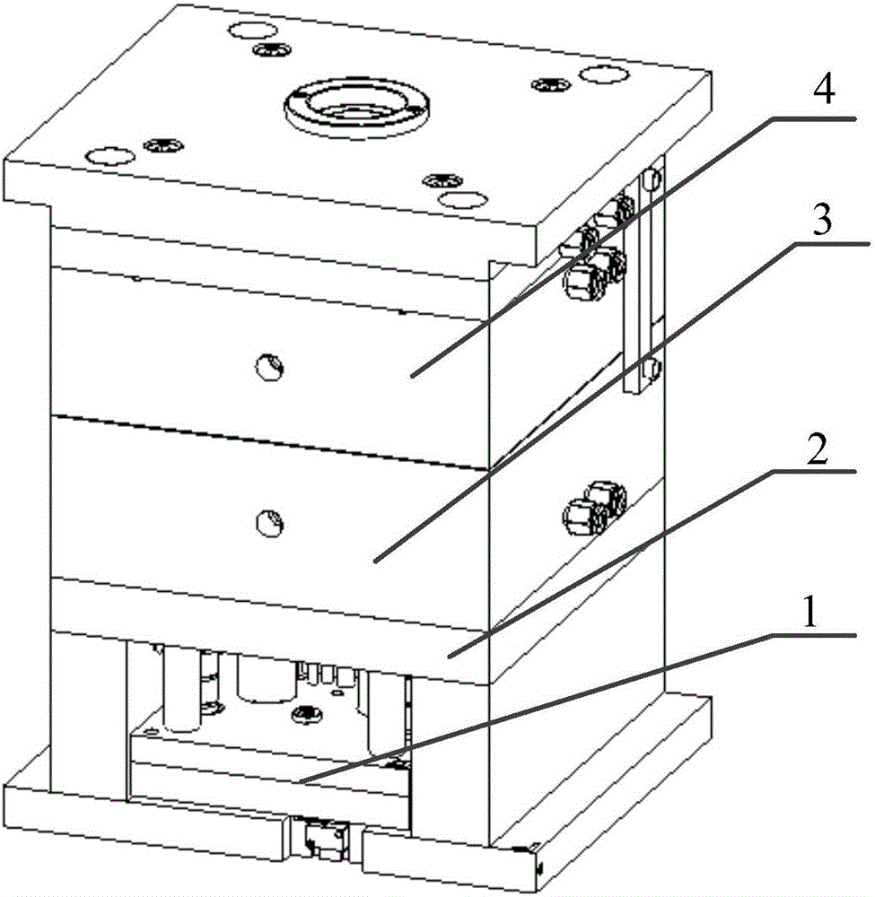
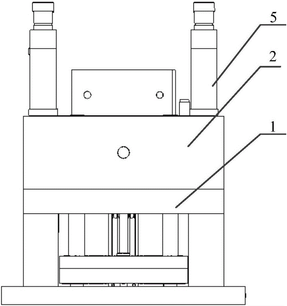
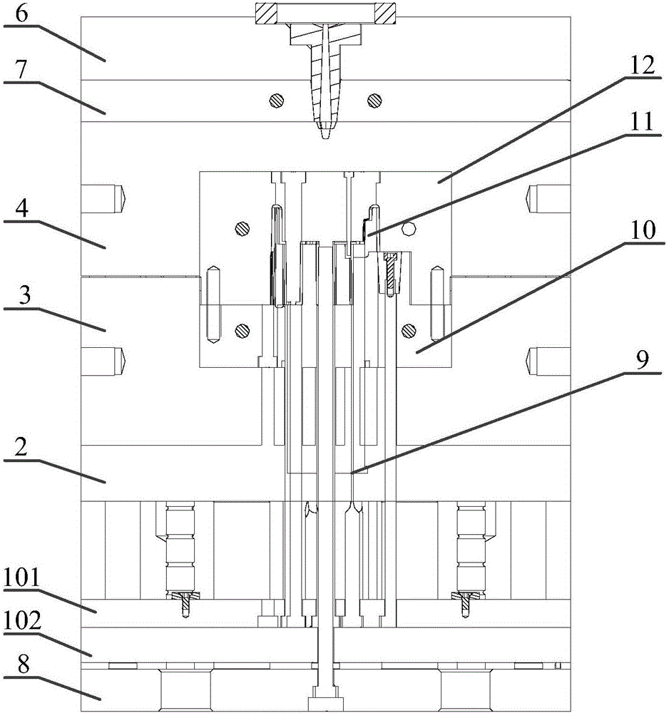
[0024] The core of the present invention is to provide an injection mold, which can ensure that the injection molded part is completely separated from the rear mold assembly.

[0025] Please refer to Figure 1 to Figure 3 , figure 1 Is a schematic structural diagram of a specific embodiment of the injection mold provided by the present invention; figure 2 Is a partial structural diagram of a specific embodiment of the injection mold provi...


PUM


Abstract

The invention discloses an injection mould. The injection mould comprises an ejection system, a rear template and a rear mould insert arranged in the rear template and also comprises a base plate, wherein the base plate is fixedly arranged on the ejection system, the rear mould insert is fixed at the base plate, the rear template is arranged on the base plate, and a control member used for controlling the rear template to move far away from the base plate when the mould is opened is arranged between the rear template and the base plate. According to the injection mould disclosed by the invention, the base plate is additionally arranged, and the rear template is changed into a float plate form, so that a deep rib circle glue position of an injection part is drawn out firstly before a product is ejected, the ejection is smooth by utilizing the action, the quality of the injection part is stable, and the injection part can be ensured to be intactly separated from a rear mould assembly.

Description

Technical field [0001] The invention relates to the technical field of mechanical processing, in particular to an injection mold. Background technique [0002] In modern mechanical transmission, a pressure lubrication system is often used to provide the necessary lubrication conditions for the transmission mechanism to ensure the normal operation of the transmission mechanism. [0003] The injection molded parts are left in the back mold too high and the circumference has deep ribs, and the packing force is large. During the reproduction process, the product is prone to deformation and damage when the product is ejected. [0004] Therefore, how to ensure that the injection molded part is completely separated from the rear mold assembly is a technical problem that needs to be solved by those skilled in the art. Summary of the invention [0005] In view of this, the purpose of the present invention is to provide an injection mold that can ensure that the injection molded part is comple...

Claims


Application Information

Patent Timeline
Patent Type & Authority Applications(China)
IPC IPC(8): B29C45/33B29C45/40
CPCB29C45/33B29C45/401
Inventor 南基学严永满罗墩涛
Owner DONGGUAN YEJIA ELECTRONICS TECH
Why Eureka
Try Eureka