Double pneumatic punch needle device

A double-pneumatic, stamping needle technology, applied in printing, typewriters, manufacturing tools, etc., can solve problems such as unsatisfactory use requirements, many marking contents, and slow speed, so as to avoid mutual wear, enhance accuracy, and reduce mechanical contact. Effect

Active Publication Date: 2017-02-22
SHANTOU JUNGUO MECHANICAL & ELECTRICAL TECH CO LTD
View PDF6 Cites 3 Cited by
  • Summary
  • Abstract
  • Description
  • Claims
  • Application Information

AI Technical Summary

Problems solved by technology

In the practical application of the pneumatic marking machine, it is often necessary to mark the object to be marked on the fast-paced production line, and the marking content is large and the font is large; in this case, the single-needle pneumatic marking machine appears to be slow Weaknesses that cannot meet the requirements for use

Method used


Image

  • Double pneumatic punch needle device
  • Double pneumatic punch needle device
  • Double pneumatic punch needle device

Examples


Embodiment Construction

[0021] In order to allow the purpose, features and functions of the present invention to be further understood, the present invention will be further described in conjunction with specific embodiments and accompanying drawings:

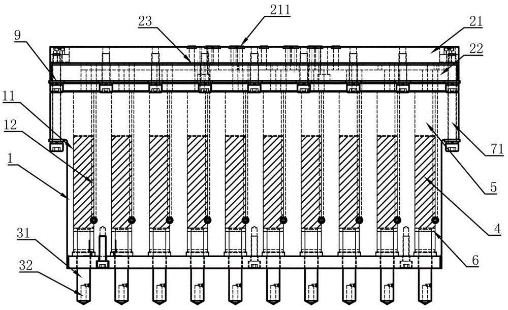
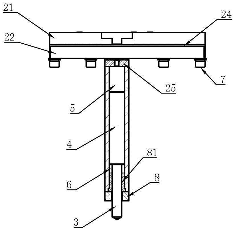
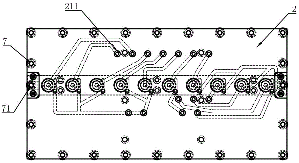
[0022] Such as Figure 1-4 , a double pneumatic punching needle device, comprising: a punching needle base, an air circuit board and a punching needle part, the punching needle base is installed at the bottom of the air circuit board, a piston rod is arranged inside the punching needle base, and the bottom of the piston rod is installed Punching parts, the top of the piston rod and the air circuit board form the upper air chamber, the bottom of the piston rod and the punch seat form the lower air chamber, the air circuit of the air circuit board is connected with the upper air chamber and the lower air chamber separately, controlled by double air pumps The air volume inside the upper air cavity and the lower air cavity is quickly inflated to press dow...


PUM


Abstract

The invention relates to the field of a pneumatic marking machine, and more particularly to a double pneumatic punch needle device. A punch needle base is mounted at the bottom of an air board. A piston rod is disposed in the punch needle. The bottom of the piston rod is equipped with a punch needle member. The top of the piston rod forms an upper air chamber with the air board. The bottom of the piston rod forms a lower air chamber with the punch needle base. The air channel of the air board communicates with the upper air chamber and the lower air chamber separately. The marking action is completed by controlling the air volume of the upper air chamber and the lower air chamber with a double air pump and by rapid inflation to make the punch needle member to press downward. The invention is at least advantageous in that the punch needle device reduces the mechanical contact and avoids the mutual wear among parts, thereby reducing the number of mechanical spare parts; and by adopting the double air pump to provide power, the punch needle device is designed to save energy and reduce loss, with the cooperation of a punch needle limit plate and a punch needle limit sleeve, the accuracy of the marking process is enhanced, the deformation or aging of the mechanical parts will not result in the change of mechanical performance, and the service life of the punch needle device is greatly increased.

Description

technical field [0001] The invention relates to the technical field of pneumatic marking machines, in particular to a double pneumatic punching needle device. Background technique [0002] In the processing of steel plate coils, in order to ensure the quality control of steel products, it is often necessary to print the numbers of these steel products, so as to trace back the origin, processing party, transporter and manufacturer of steel products, as well as the classification and application of steel products. It plays an indispensable role in the production management control of the enterprise. In the case of unclear or missing markings, the steel may not be recognized by customers because it is difficult to trace back and the quality is difficult to guarantee, resulting in related upstream production and processing of steel. loss to practitioners. [0003] Pneumatic marking machine is suitable for marking pictures and texts on metal and non-metal materials. It is widely...

Claims


Application Information

Patent Timeline
Patent Type & Authority Applications(China)
IPC IPC(8): B41J2/225B41J3/413B41J3/407B21C51/00
CPCB21C51/005B41J2/225B41J3/4073B41J3/413
Inventor 罗俊生
Owner SHANTOU JUNGUO MECHANICAL & ELECTRICAL TECH CO LTD
Why Eureka
Try Eureka