Escaping window structure

A technology of escape windows and structural holes, which is applied in the field of escape window structures, can solve problems such as deficiencies, and achieve the effects of reasonable structure, reliable positioning, and convenient opening and operation.

Inactive Publication Date: 2017-02-22
吴渭尧
View PDF9 Cites 1 Cited by
  • Summary
  • Abstract
  • Description
  • Claims
  • Application Information

AI Technical Summary

Problems solved by technology

However, the current car escape window structure is still lacking in terms of e

Method used


Image

  • Escaping window structure
  • Escaping window structure
  • Escaping window structure

Examples


Embodiment 1

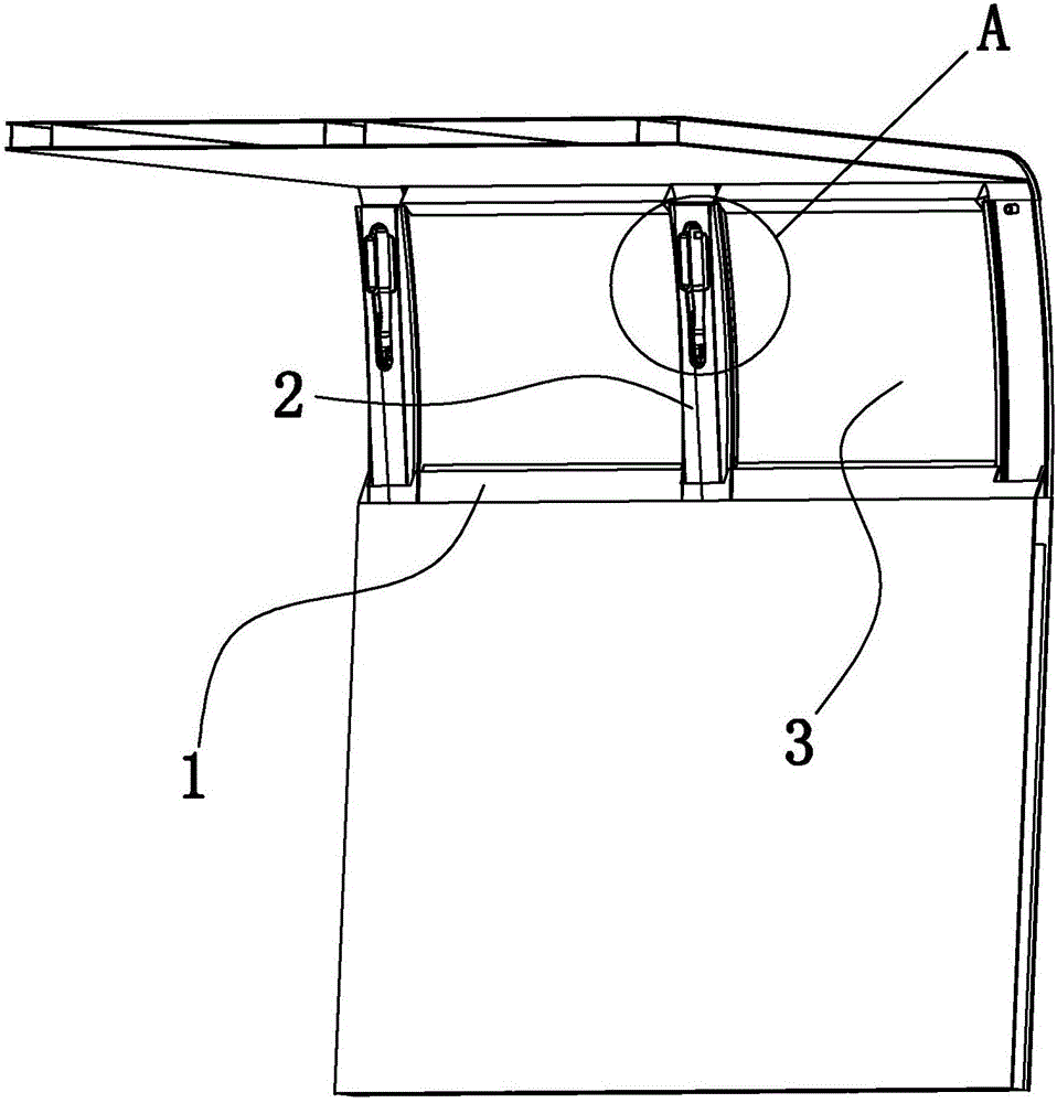
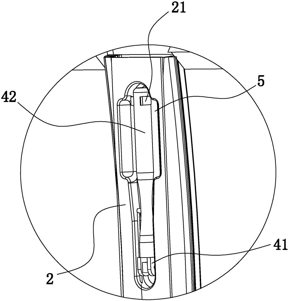
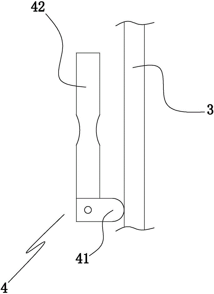
[0025] Example 1: Such as Figure 1 to Figure 5 In the illustrated embodiment, an escape window structure includes a window frame 1, a compression frame connected to the window frame 2, an escape window 3 arranged in the window frame, and a window accommodating cavity for accommodating the escape window , The window accommodating cavity is arranged on the car body, the escape window is slidingly matched with the window frame and the slidable direction of the escape window is up and down, the window accommodating cavity is under the escape window, and the window frame is provided for escape The drop hole through which the window passes, the drop hole communicates with the window accommodating cavity, the pressing frame is provided with a pressing body 4 for pressing the escape window, the pressing body is rotatably connected with the pressing frame, and the pressing body contacts the escape window body. Escape windows are mostly made of glass, that is, glass windows, which can a...

Embodiment 2

[0031] Example 2: The basic structure and implementation of this example are the same as Example 1, the difference lies in Figure 6 to Figure 8 As shown in the figure, the compression frame is provided with a power cylinder 6, a power piston 61 that is slidingly sealed and matched with the power cylinder, and a main piston rod 62 connected to the power piston and used for contacting the cam lever. The main piston rod is in power Above the piston, the top end of the main piston rod is in the structure hole, and the window frame is provided with at least one pushing cylinder 7 for pushing the escape window downwards. The pushing cylinder is provided with a pushing piston 71 that cooperates with the sliding seal of the pushing cylinder to push The piston is provided with a secondary piston rod 72 under the pushing piston. The lower end of the secondary piston rod contacts the top of the escape window. The power cylinder is divided into a power chamber 6a and a main hydraulic chamb...


PUM


Abstract

The invention discloses an escaping window structure. The escaping window structure comprises a window frame, a compacting framework connected with the window frame, an escaping window body arranged in the window frame, and a window body accommodating cavity for accommodating the escaping window body, wherein the escaping window body is sliding fit to the window frame, and the escaping window body slides in an up-and-down direction; the window body accommodating cavity is located under the escaping window body; a falling hole allowing the escaping window body to pass through is formed in the window frame, and communicates with the window body accommodating cavity; a compacting body for compacting the escaping window body is arranged on the compacting framework, and is in rotary connection with the compacting framework; and the compacting body is in contact with the escaping window body. The escaping window structure disclosed by the invention has the beneficial effects that the structure is reasonable; when being not in use, the automobile escaping window is reliable to position and stable in structure; and while in use, the automobile escaping window can be quickly opened through simple action, the opening operation is convenient, disruptive opening is not needed, the escaping effect can be guaranteed, and the escaping window structure can be effectively recovered and reused.

Description

Technical field [0001] The invention belongs to the technical field of vehicle escape structures, and particularly relates to an escape window structure. Background technique [0002] At present, in automobiles, especially buses, escape window structures are often installed to allow people in the vehicle to escape through the escape windows when accidents, disasters, and other situations occur. The current escape window structure is more common in the form of a closed window with a safety hammer, that is, when an escape is needed, the escape window (glass) is smashed with a safety hammer, and then the car is left. However, the current car escape window structure is still lacking in terms of ease of use, opening time, difficulty of opening, and improved escape effect. Summary of the invention [0003] In order to overcome the shortcomings in the prior art, the present invention provides an escape window structure that is reasonable in structure, can be quickly opened when needed, ...

Claims


Application Information

Patent Timeline
IPC IPC(8): B60J1/00E05F15/53
CPCB60J1/00E05F15/53
Inventor 吴渭尧
Owner 吴渭尧
Why Eureka
Try Eureka