A hydrogen power energy system

A technology of electric energy and hydrogen energy, which is applied in the field of energy systems and hydrogen energy systems, can solve the problems of being unable to promote, consuming other resources, and being expensive

Active Publication Date: 2019-06-04
SHIJIAZHUANG XINHUA IND FURNACE CO LTD
View PDF7 Cites 0 Cited by
  • Summary
  • Abstract
  • Description
  • Claims
  • Application Information

AI Technical Summary

Problems solved by technology

The promotion of hydrogen energy power needs to solve three technical problems: one is to produce a large amount of cheap hydrogen, the traditional electrolysis method is expensive and consumes other resources, so it cannot be promoted; the second is the safe storage and transportation of hydrogen; the third is the high High-performance, inexpensive hydrogen supply system

Method used


Image

  • A hydrogen power energy system
  • A hydrogen power energy system
  • A hydrogen power energy system

Examples


Embodiment 1

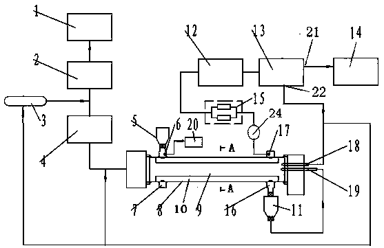
[0022] The hydrogen power energy system of the present invention is as figure 1As shown, it includes coal powder silo 5, partition wall rotary kiln 8, waste heat power generation unit 4 with desulfurization equipment, high-pressure low calorific value fuel preparation unit 1, gas booster device 2, reducing gas storage tank 3, and steam generator 20 , a desulfurization device 15, a gas component analyzer 24, a water spray dust collector 12, a hydrogen extraction device 13 and a hydrogen energy preparation unit 14. The partition wall rotary kiln includes a kiln body, a kiln head cover, a kiln tail cover, a coke powder hopper 11, a feeding ring 7 and a discharge ring 16. The kiln body is composed of a kiln chamber 9 and an annular material passage 10. Ring material channel connection. The kiln hood is provided with a gas fuel burner 18 and a solid fuel burner 19 . The pulverized coal silo is connected to the feed ring, and the discharge ring is connected to the solid fuel burne...

Embodiment 2

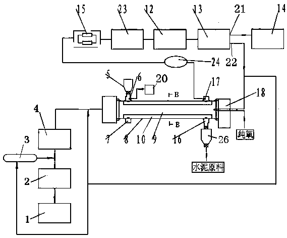
[0025] Another embodiment of the present invention is as figure 2 As shown, it includes coal powder silo 5, partition wall rotary kiln 8, waste heat power generation unit 4 with desulfurization equipment, high-pressure low calorific value fuel preparation unit 1, gas booster device 2, reducing gas storage tank 3, and steam generator 20 , desulfurization device 15, water spray dust collector 12, denitrification device 23, gas composition analyzer 24, hydrogen extraction device 13 and hydrogen energy preparation unit 14. The partition wall rotary kiln includes a kiln body, a kiln head cover, a kiln tail cover, a gasification residue bin 26, a feeding ring 7 and a discharge ring 16. The kiln body is composed of a kiln chamber 9 and a straight material channel 30. Connect with straight material channel. The kiln tail cover is provided with a gas fuel burner 18 . The pulverized coal silo is connected to the feed ring, and the discharge ring is connected to the cement raw materia...

Embodiment 3

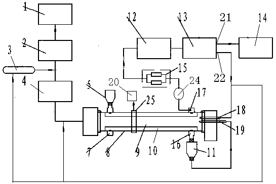
[0028] The third embodiment of the present invention is as image 3 As shown, it includes coal powder silo 5, partition wall rotary kiln 8, waste heat power generation unit 4 with desulfurization equipment, high-pressure low calorific value fuel preparation unit 1, gas booster device 2, reducing gas storage tank 3, and steam generator 20 , a gas component analyzer 24, a desulfurization device 15, a water spray dust collector 12, a hydrogen extraction device 13 and a hydrogen energy preparation unit 14. The partition wall rotary kiln includes a kiln body, a kiln head cover, a kiln tail cover, a coke powder hopper 11, a feeding ring 7 and a discharge ring 16. The kiln body is composed of a kiln chamber 9 and an annular material passage 10. Ring material channel connection. The kiln hood is provided with a gas fuel burner 18 and a solid fuel burner 19 . The pulverized coal silo is connected to the feed ring, and the discharge ring is connected to the solid fuel burner through t...


PUM

PropertyMeasurementUnit
particle sizeaaaaaaaaaa

Abstract

The invention relates to a hydrogen electricity energy system. The system comprises a pulverized coal bin, a waste heat power generation unit provided with a desulfurizing device, a desulfurizer, a water spraying dust remover, a hydrogen extracting device, a partition rotary kiln and a hydrogen energy preparation unit, wherein a kiln head hood is provided with a gas fuel nozzle and / or a solid fuel nozzle; the pulverized coal bin is connected to a charging ring, and a discharging ring is connected to the solid fuel nozzle through the pulverized coal bin; a steam generator is connected with a gasifying agent inlet, and a gasifying agent outlet is connected to the hydrogen extracting device through the desulfurizer and the water spraying dust remover; a hydrogen outlet and an after-hydrogen-extraction fuel outlet are formed in the hydrogen extracting device, the hydrogen outlet is connected to the hydrogen energy preparation unit, one way of the after-hydrogen-extraction fuel outlet is connected to a reducing gas storage tank, one way is connected to the gas fuel nozzle, and another way is connected with an inlet of the waste heat power generation unit provided with the desulfurizing device. The partition rotary kiln is taken as gasification equipment, steam is injected to gasify all tar, coal gas after hydrogen sulfide removal and hydrogen extraction is sent to the hydrogen energy preparation unit, so that clean utilization of coal is realized, and hydrogen energy cost is reduced.

Description

technical field [0001] The invention belongs to the technical field of energy equipment and relates to an energy system, in particular to a hydrogen electric energy system. Background technique [0002] Gasoline and diesel are non-renewable resources. In order to alleviate a series of negative effects brought about by the shortage of petroleum resources and reduce air pollution and vehicle engine exhaust emissions, it is necessary to find alternative fuels for engines, and hydrogen energy is currently the most ideal clean fuel. . Hydrogen energy is a renewable resource among many alternative energy sources. It has a high calorific value and most of the products after combustion are water vapor. It is an ideal green fuel. Hydrogen energy as an alternative fuel can solve two major problems: one is the limited reserves of petroleum fuels, and the other is the environmental pollution caused by the use of petroleum fuels. [0003] The advantage of hydrogen as a fuel is that it ...

Claims


Application Information

Patent Timeline
Patent Type & Authority Patents(China)
IPC IPC(8): C10J3/60C10J3/72C10J3/84C01B6/00
CPCC01B6/00C10J3/60C10J3/72C10J3/84C10J2200/15C10J2300/093C10J2300/0976C10J2300/1223C10J2300/1603C10J2300/1671C10J2300/1807Y02P20/129
Inventor 贾会平
Owner SHIJIAZHUANG XINHUA IND FURNACE CO LTD
Why Eureka
Try Eureka