Template used for casting floor beam and construction method of floor beam
A construction method and technology of floor beams, which are applied in the fields of formwork/formwork/work frame, on-site preparation of building components, construction, etc., can solve the problems of floor beam explosion, large formwork gap, and expansion of the formwork, etc., so as to avoid the expansion. mold, prevent mold expansion, reduce the effect of load
- Summary
- Abstract
- Description
- Claims
- Application Information
AI Technical Summary
Problems solved by technology
Method used
Image
Examples
Embodiment 1
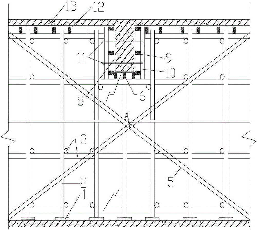
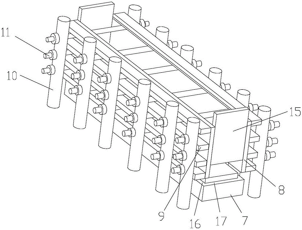
[0034] like figure 1 , 2 As shown, the present embodiment discloses a formwork for pouring floor beams, including beam bottom formwork 7 , beam side formwork 8 , beam end formwork 15 , and floor slab bottom formwork 13 . The beam bottom formwork 7, the beam end formwork 15, and the beam side formwork 8 form an open structure with an open top, closed sides and bottom. Floor bottom formwork 13 is arranged on the side of beam side formwork 8 top. Also include horizontal back corrugated 9, clamping piece. The horizontal back flute 9 is limited between the clamping piece and the side of the beam side formwork 8 .
[0035] When pouring and vibrating, since the present invention is provided with horizontal back corrugations 9 on both sides of the beam side formwork 8, when the beam side formwork 8 is stressed, part of the force can be dispersed to the horizontal back corrugations 9, thereby reducing the The load of the formwork 8 effectively prevents the phenomenon of mold expans...
Embodiment 2
[0040] like figure 1 , 2 As shown, the present embodiment discloses a formwork for pouring floor beams, including beam bottom formwork 7 , beam side formwork 8 , beam end formwork 15 , and floor slab bottom formwork 13 . The beam bottom formwork 7, the beam end formwork 15, and the beam side formwork 8 form an open structure with an open top, closed sides and bottom. Floor bottom formwork 13 is arranged on the side of beam side formwork 8 top. Also include horizontal back corrugated 9, clamping piece. The horizontal back flute 9 is limited between the clamping piece and the side of the beam side formwork 8 . The beam side formwork installation structure 16 and the beam end formwork installation structure 17 are reserved on the edge of the beam bottom formwork 7 top, the width of the formwork installation structure is the same as the thickness of the beam side formwork 8, and the width of the beam end formwork installation structure 17 is the same as that of the beam end for...
Embodiment 3
[0043] like figure 1 , 2 As shown, the present embodiment discloses a formwork for pouring floor beams, including beam bottom formwork 7 , beam side formwork 8 , beam end formwork 15 , and floor slab bottom formwork 13 . The beam bottom formwork 7, the beam end formwork 15, and the beam side formwork 8 form an open structure with an open top, closed sides and bottom. Floor bottom formwork 13 is arranged on the side of beam side formwork 8 top. Also include horizontal back corrugated 9, clamping piece. The horizontal back flute 9 is limited between the clamping piece and the side of the beam side formwork 8 . The beam side formwork installation structure 16 and the beam end formwork installation structure 17 are reserved on the edge of the beam bottom formwork 7 top, the width of the formwork installation structure is the same as the thickness of the beam side formwork 8, and the width of the beam end formwork installation structure 17 is the same as that of the beam end for...
PUM
 Abstract
Description
Claims
Application Information
 - R&D
- Intellectual Property
- Life Sciences
- Materials
- Tech Scout
- Unparalleled Data Quality
- Higher Quality Content
- 60% Fewer Hallucinations
Browse by: Latest US Patents, China's latest patents, Technical Efficacy Thesaurus, Application Domain, Technology Topic, Popular Technical Reports.
© 2025 PatSnap. All rights reserved.Legal|Privacy policy|Modern Slavery Act Transparency Statement|Sitemap|About US| Contact US: help@patsnap.com


