Main driving device of angle adjustable shield tunneling machine

A shield machine, adjustable technology, applied in mining equipment, earthwork drilling, tunnels, etc., can solve the problems of increased angle between the shield body and the segment, insufficient weight, damage to the assembled segments, etc., to simplify the cutter head Structure, the effect of saving manufacturing cost

Active Publication Date: 2017-02-22
JIANGSU KAIGONG TUNNEL MACHINERY
View PDF4 Cites 8 Cited by
  • Summary
  • Abstract
  • Description
  • Claims
  • Application Information

AI Technical Summary

Problems solved by technology

Due to insufficient weight at the front of the shield machine or excessive radial soil pressure, the cutter head of the shield machine will float or sink during the excavation process, resulting in damage to the assembled segments, and may also cause the actual position of the tunnel to be inconsistent with the design plan , therefore, the attitude of the shield machine must be adjusted when the cutter head of the shield machine is floating or sinking, so that the actual position of the tunnel is consistent with the design
In the actual operation process, the posture adjustment of the shield machine is mainly realized by the telescopic stroke difference of the propulsion cylinder and the steering of the cutterhead. Angle increases, resulting in segment damage and misalignment
[0003] At the same time, the shield machine needs to use the super digging knife or the profiling knife to perform over digging when turning. To realize the super digging function, the cutter head must be equipped with components such as oil cylinders to provide the power for the super digging knife or the profiling knife to expand and contract. At the same time, it is necessary to design corresponding pipelines, detection devices, etc., which increases the manufacturing cost of the cutter head and makes the overall structure of the cutter head complicated.

Method used


Image

  • Main driving device of angle adjustable shield tunneling machine
  • Main driving device of angle adjustable shield tunneling machine
  • Main driving device of angle adjustable shield tunneling machine

Examples


Embodiment Construction

[0026] A preferred embodiment of the present invention will be described in detail below in conjunction with the accompanying drawings. However, the scope of protection of the present invention is not limited to the following examples, that is, any simple equivalent changes and modifications made based on the patent scope of the present invention and the content of the description are still within the scope of the patent of the present invention.

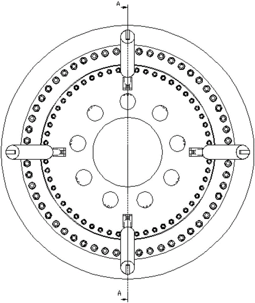
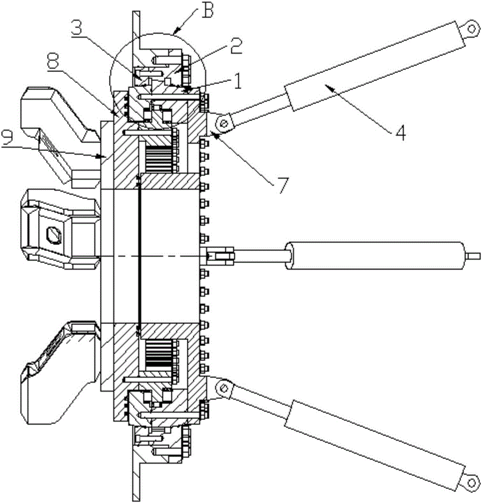
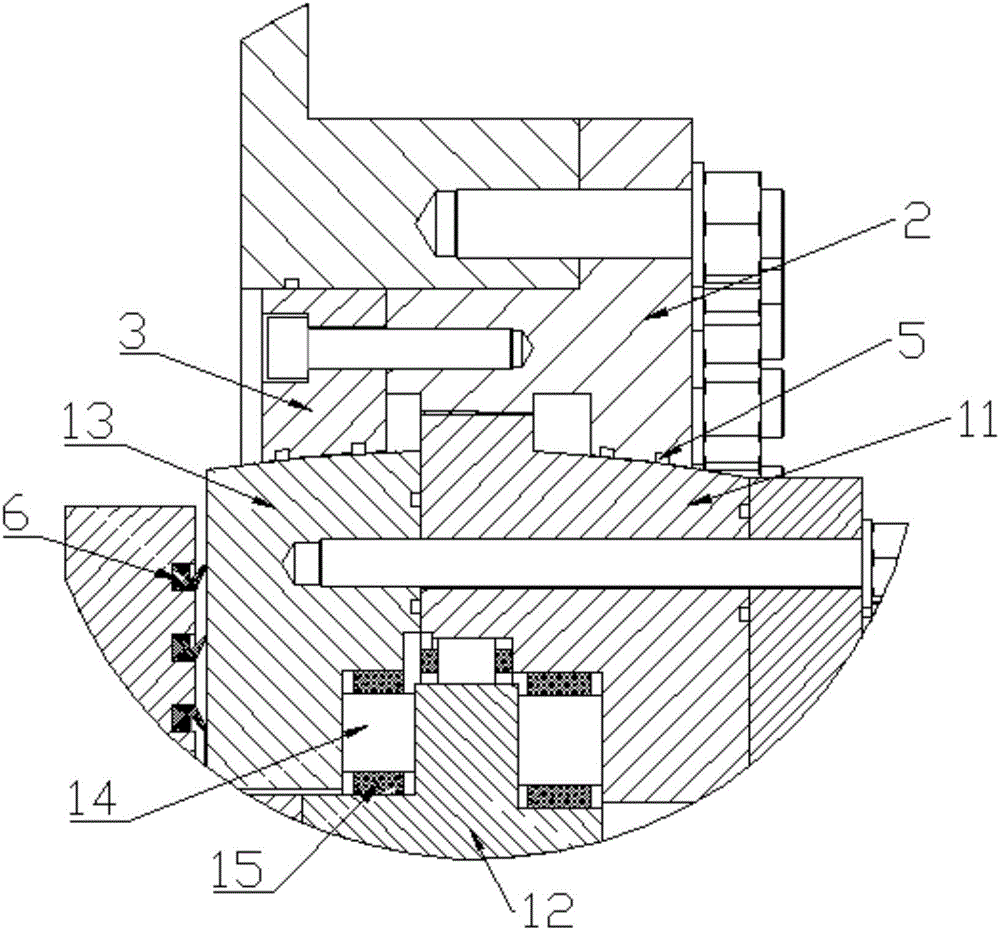
[0027] A main driving device of an angle-adjustable shield machine, including an outer spherical main bearing 1, an inner spherical main bearing mounting seat 2, an inner spherical main bearing mounting seat 3, an angle adjustment oil cylinder 4, an O-shaped sealing ring 5, and an end face sealing ring 6 , oil cylinder mount 7, seal mount 8.

[0028] The outer spherical main bearing 1 is a three-row cylindrical roller bearing for the main drive slewing support, which is composed of a bearing base 11, a bearing ring gear 12, a bearin...


PUM


Abstract

The invention discloses a main driving device of an angle adjustable shield tunneling machine. The main driving device comprises an outer spherical surface main bearing, a first inner spherical surface main bearing mounting seat, a second inner spherical surface main bearing mounting seat, angle adjusting cylinders, a cylinder mounting seat and a sealed mounting seat, wherein the first and second inner spherical surface main bearing mounting seats are respectively matched with the outer spherical surface main bearing through spherical surfaces; totally four angle adjusting cylinders are uniformly distributed on the same circle, one end of each of the angle adjusting cylinders is hinged with the outer spherical surface main bearing, and the other end of each of the angle adjusting cylinders is hinged with the shield tunneling machine. According to the device, rising or sinking of a cutter head of the shield tunneling machine is controlled by adjusting the stroke difference of an upper cylinder and a lower cylinder, a tunneling posture of the shield tunneling machine is adjusted, a phenomenon that segment damage in a thrust posture is adjusted by a thrust cylinder is avoided, and the tunneling direction of the shield tunneling machine can be accurately controlled; meanwhile, the over-excavation amount of the cutter head can be adjusted by adjusting the stroke difference of the left and right two cylinders, so that an aim of smoothly turning the shield tunneling machine is achieved, use of the cylinders and other assemblies is avoided, the manufacturing cost is reduced, and the cutter head structure is simplified.

Description

technical field [0001] The invention relates to the technical field of shield machines, in particular to an angle-adjustable main driving device of a shield machine. Background technique [0002] The main drive of the shield machine is the power source for the cutter head to rotate when the shield machine is excavating, and it is the core system of the shield machine. During the tunneling process of the shield machine, the outer part of the main drive and the front shield body are connected together by bolts and kept fixed, and the inner part outputs rotational driving force and torque to the cutter head through the slewing support bearing to drive the rotation of the excavation cutter head. Due to insufficient weight at the front of the shield machine or excessive radial soil pressure, the cutter head of the shield machine will float or sink during the excavation process, resulting in damage to the assembled segments, and may also cause the actual position of the tunnel to ...

Claims


Application Information

Patent Timeline
Patent Type & Authority Applications(China)
IPC IPC(8): E21D9/093E21D9/08
CPCE21D9/0621E21D9/0692E21D9/08
Inventor 苏延奇徐昊朗李留涛韩真
Owner JIANGSU KAIGONG TUNNEL MACHINERY
Why Eureka
Try Eureka