Spring fixing structure of rolling rotor compressor and rolling rotor compressor

A rolling rotor type, spring-fixed technology, applied in the field of compressors, can solve problems such as spring failure and deformation, and achieve the effect of ensuring sealing

Active Publication Date: 2018-10-02
ZHUHAI GREE REFRIGERATION TECH CENT OF ENERGY SAVING & ENVIRONMENTAL PROTECTION
View PDF7 Cites 0 Cited by
  • Summary
  • Abstract
  • Description
  • Claims
  • Application Information

AI Technical Summary

Problems solved by technology

As a result, the spring is easily deformed at these supporting parts during high-frequency reciprocating motion, and eventually the spring fails to work.

Method used


Image

  • Spring fixing structure of rolling rotor compressor and rolling rotor compressor
  • Spring fixing structure of rolling rotor compressor and rolling rotor compressor
  • Spring fixing structure of rolling rotor compressor and rolling rotor compressor

Examples


Embodiment 1

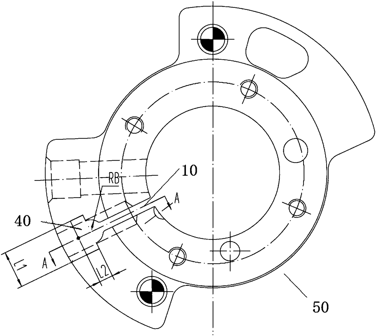
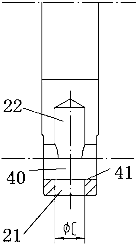
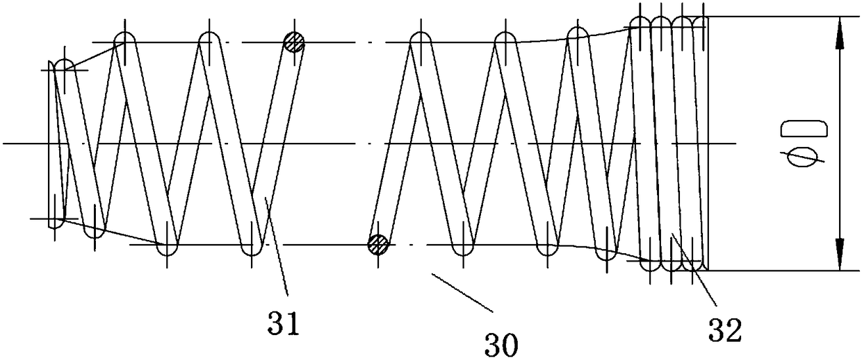
[0042] This embodiment provides a spring fixing structure for a rolling rotor compressor, such as figure 1 , figure 2 As shown, it includes: a spring hole 20 formed on the body of the cylinder 50, extending radially from the outer wall surface of the cylinder 50 to the slide groove 10 where the slide is installed; a fixed cavity 40 formed on the body of the cylinder 50, which is The spring hole 20 is close to the outer wall surface of the cylinder 50 and is composed of an enlarged part along the aperture; the spring 30 has a biasing part 31 which is arranged in the spring hole 20 and can be freely expanded and contracted, and a connected radially enlarged fixing part 32 , the biasing end of the biasing part 31 is against the sliding plate, the diameter of the fixing part 32 is larger than the diameter of the spring hole 20 and is supported in the fixing cavity 40; the fixing cavity 40 resists the The contact part 41 of the spring 30 is a plane, so that the fixed part 32 of t...

Embodiment 2

[0052] A rolling rotor compressor provided in this embodiment includes: a cylinder 50, rollers are arranged in the cylinder 50, a sliding vane groove 10 is opened on the cylinder 50, and a sliding vane groove 10 is arranged in the sliding vane groove 10. A spring hole 20 communicating with the slide groove 10 is formed on the outer wall of the cylinder 50. One end of the spring 30 is against the slide, and the other end is fixed in the spring hole by the spring fixing structure in Embodiment 1. 20, thereby having all the advantages described in Embodiment 1.


PUM


Abstract

The invention discloses a spring fixing structure of a rolling rotor type compressor and the rolling rotor type compressor, and belongs to the technical field of compressors. The spring fixing structure of the rolling rotor type compressor comprises a spring hole, a fixing chamber and a spring, wherein the spring hole is formed in a cylinder body and extends from the outer wall surface into a slip sheet groove used for mounting a slip sheet in the radial direction of a cylinder; the fixing chamber is formed in the cylinder body and structured by a part, close to the outer wall surface of the cylinder, of the spring, wherein the part is enlarged along the spring hole diameter; the spring is provided with a partial pressing part which can be freely telescoped and is arranged in the spring hole and a radially-enlarged fixing part which is connected with the partial pressing part; a partial pressing end of the partial pressing part abuts against the slip sheet; the diameter of the fixing part is larger than that of the spring hole, and the fixing part is supported into the fixing chamber; a part, abutting against the spring, of the fixing chamber, is a plane through which the fixing part of the spring can be stably propped, and thus the spring can be continuously and effectively fixed, and as a result, the sealing between the slip sheet and a roller can be ensured.

Description

technical field [0001] The invention relates to a spring fixing structure of a rolling rotor compressor and the rolling rotor compressor, belonging to the technical field of compressors. Background technique [0002] In order to form a pressure difference when the rolling rotor compressor is started, the arc surface of the sliding vane needs to be in contact with the rolling piston to separate the cylinder into an exhaust chamber and a suction chamber. To ensure the sealing of the sliding vane and the roller, it is necessary to A spring is added to the end of the piece to make the slide piece bear on the roller. Traditionally, the spring is fixed by the interference fit between the spring tail and the spring hole. A housing is installed on the end surface of the spring hole tail. When the spring tail is separated from the spring hole, the housing can block the spring to prevent it from further detaching from the spring hole. Spring failure is avoided. Then, with the contin...

Claims


Application Information

Patent Timeline
Patent Type & Authority Patents(China)
IPC IPC(8): F04C18/356F04C29/00
CPCF04C18/3562F04C29/00F04C2240/80
Inventor 徐豪卢林高刘亮闫超董辉
Owner ZHUHAI GREE REFRIGERATION TECH CENT OF ENERGY SAVING & ENVIRONMENTAL PROTECTION
Why Eureka
Try Eureka