Valve rod assembly on electronic expansion valve

A technology of electronic expansion valve and valve stem, which is applied in the direction of refrigeration components, valve devices, engine components, etc., can solve the problems of high cost, achieve the effects of reducing cost, preventing the increase of gas leakage, and eliminating axial pressure

Pending Publication Date: 2017-02-22
ZHUJI YIBA ELECTRONICS VALVE
View PDF10 Cites 3 Cited by
  • Summary
  • Abstract
  • Description
  • Claims
  • Application Information

AI Technical Summary

Problems solved by technology

Higher precision requirements require high investment

Method used


Image

  • Valve rod assembly on electronic expansion valve
  • Valve rod assembly on electronic expansion valve
  • Valve rod assembly on electronic expansion valve

Examples


Embodiment Construction

[0030] The technical solutions of the present invention will be further specifically described below through the embodiments and in conjunction with the accompanying drawings.

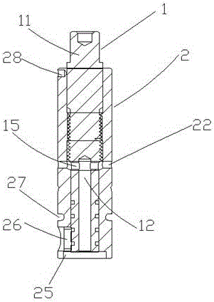
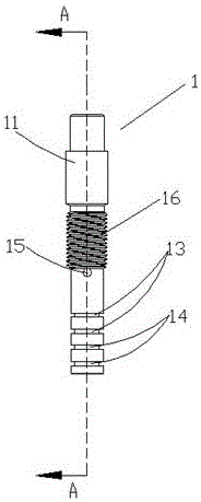
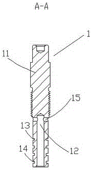
[0031] Such as figure 1 , figure 2 , image 3 , Figure 4 with Figure 5 As shown, a valve stem assembly on an electronic expansion valve includes a valve stem 1 and a bearing seat 2. The threaded section 16, the bearing seat 2 includes a seat body 23, a through hole 21 is formed in the seat body 23, the through hole 21 matches the valve stem 1, and is formed in the middle of the inner wall of the through hole 21 The internal thread section 24 matched with the external thread section 16 is matched with the external thread section 16 through the internal thread section 24 during installation, and the thread rotation between the two can be adjusted to a certain extent. By measuring the uppermost end of the bearing seat and the top of the valve stem The distance between them is used to determine the...


PUM


Abstract

The invention discloses a valve rod assembly on an electronic expansion valve. The valve rod assembly comprises a valve rod and a bearing pedestal. The valve rod is arranged in a through hole of the bearing pedestal. The valve rod assembly is characterized by comprising a rod body, an inner axial hole column is formed at the middle and lower end of the rod body, a first transverse hole column communicated with the inner axial hole column is formed on the outer wall of the bottom of the inner axial hole column, and a second transverse shaft hole communicated with the through hole is formed in the middle of the wall body of the bearing pedestal. The valve rod assembly can eliminate axial pressure born by the valve rod, moreover, the good sealing effect is achieved, and meanwhile the cost is reduced to meet the market requirements.

Description

technical field [0001] The invention relates to a valve stem assembly on an electronic expansion valve. Background technique [0002] At present, there are many types of electronic expansion valves at home and abroad, with different structural features, but their throttling structures are similar, mainly the cone valve structure. When the valve stem inside the electronic expansion valve moves axially towards the fully closed direction, when the valve needle inside the electronic expansion valve contacts the valve hole below, the valve stem begins to generate an axial pressure on the valve needle. When the electronic expansion valve is in the fully closed state, the axial pressure between the valve stem and the valve needle reaches the maximum. This is because the valve needle is in a static state when the valve needle is in the fully closed state, and the spring inside the valve stem is under pressure. The downward pressure of the valve stem compresses the spring; when th...

Claims


Application Information

Patent Timeline
Patent Type & Authority Applications(China)
IPC IPC(8): F16K51/00F25B41/06F25B41/34
CPCF16K51/00F25B41/31Y02B30/70
Inventor 何孝水陈华军
Owner ZHUJI YIBA ELECTRONICS VALVE
Why Eureka
Try Eureka