Lifting offshore wind driven generator

A technology for wind turbines and wind turbines, which is applied in the directions of wind turbines, wind energy power generation, and the configuration of installing/supporting wind turbines, can solve problems such as the influence of the service life of the lifting tower, the reduction of the efficiency of downgrading, and the unstable structure, etc. Achieve the effect of improving service life, ensuring stability and improving maintenance efficiency

Inactive Publication Date: 2020-12-25
周德旺
View PDF14 Cites 0 Cited by
  • Summary
  • Abstract
  • Description
  • Claims
  • Application Information

AI Technical Summary

Problems solved by technology

[0004] The wind turbine is a large-scale equipment, and the lifting structure of the device is not stable enough only through the meshing transmission, which may cause the risk of the fan falling;
[0005] At the same time, in the process of overhauling the wind power generating set, it is necessary to manually climb to the generating set and then carry out maintenance operations on it. Because manual climbing is required, it will cause certain dangers and also Reduced repair efficiency;
[0006] Most of the lift towers are in the stretched state during the power generation process, so it needs to be eroded by the sea wind for a long time, which will have a certain impact on the service life of the lift tower

Method used


Image

  • Lifting offshore wind driven generator
  • Lifting offshore wind driven generator
  • Lifting offshore wind driven generator

Examples


Embodiment Construction

[0084] The following description serves to disclose the present invention to enable those skilled in the art to carry out the present invention. The preferred embodiments described below are only examples, and those skilled in the art can devise other obvious variations.

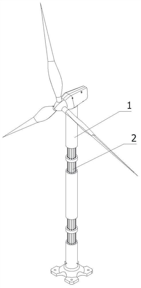
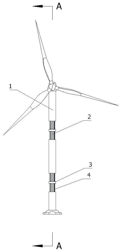
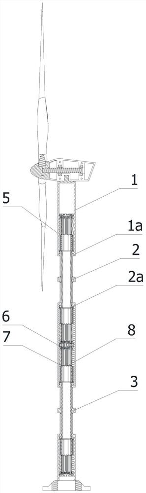
[0085] refer to Figure 1 to Figure 15 As shown, a lifting offshore wind power generator includes a base, and is characterized in that it includes an intelligent wind power generating set 9 and an intelligent lifting tower;

[0086] The intelligent wind power generating set 9 includes a lifting module 91 and a lifting frame 92;

[0087] The intelligent lifting tower includes: a multi-section outer support tower 1, an inner support tower 2, a fixed edge 3, a sliding column 4, a hydraulic abutment mechanism 5, an elastic damping mechanism 6, a sliding limit cylinder 7, and a screw limiter. Bit mechanism 8, atomization module 31;

[0088] The multi-section outer support tower 1 and the inner support tower 2 ...


PUM


Abstract

The invention relates to the technical field of new energy equipment, and particularly relates to a lifting offshore wind driven generator. The lifting offshore wind driven generator comprises a winddriven generator set and a base, and further comprises a duplex reverse lifting tower, a fixed edge, sliding column pieces, a hydraulic abutting mechanism, an elastic damping mechanism, sliding limiting cylinders and lead screw limiting mechanisms, wherein the duplex reverse lifting tower comprises a plurality of sections of outer supporting towers and inner supporting towers, the supporting towers are coaxially arranged in a sliding manner at intervals, and a first limiting edge and a second limiting edge are coaxially arranged at the two ends in each supporting tower correspondingly; the fixed edge is arranged on the middle section of each inner supporting tower; the sliding column pieces are evenly distributed on the fixed edge along the axis, and the two ends of each sliding column piece are in sliding fit with the upper first limiting edge and the lower first limiting edge; output parts of the hydraulic abutting mechanism are fixedly connected with the two ends of each inner supporting tower; a damping part of the elastic damping mechanism is downwards arranged in the hydraulic abutting mechanism; the sliding limiting cylinders are coaxially and fixedly arranged at the two ends of each inner supporting tower, and the outer circumferential faces of the sliding limiting cylinders are in sliding fit with driving parts of the hydraulic abutting mechanism; and the lead screw limiting mechanisms are arranged on the inner walls of the sliding limiting cylinders. The wind driven generator is stable in lifting structure and high in safety.

Description

technical field [0001] The invention relates to the technical field of new energy equipment, in particular to a lifting offshore wind power generator. Background technique [0002] A wind turbine is a power device that converts wind energy into mechanical work, which drives the rotor to rotate, and finally outputs alternating current. In a broad sense, wind energy is also solar energy, so it can also be said that a wind generator is a thermal energy utilization generator that uses the sun as a heat source and the atmosphere as a working medium. The traditional wind turbine does not have a lifting adjustment mechanism, which is not convenient for maintenance when the wind turbine fails, and it is impossible to adjust it when there is a typhoon or other destructive weather, so as to disassemble it and make the wind power Generators are easily damaged. [0003] Chinese patent CN201620785662.9 discloses a lifting and rotating mechanism of a wind power generator, which includes...

Claims


Application Information

Patent Timeline
Patent Type & Authority Applications(China)
IPC IPC(8): F03D13/25F03D80/70F16F15/04F16M11/28F16N7/32
CPCF05B2260/98F16F15/04F16M11/28F16N7/32F16N2210/025F03D13/25F03D80/70Y02E10/72Y02E10/727
Inventor 不公告发明人
Owner 周德旺
Why Eureka
Try Eureka