Steam cylinder electric control drainage device

A steam drying cylinder and electric control technology, which is applied in the field of textile dyeing and finishing, can solve the problems of increased drying time, low energy utilization rate, and increased operating cost, and achieve high measurement and control accuracy, improved hydrophobic efficiency, and improved steam utilization rate. Effect

Active Publication Date: 2017-02-22
顾金华
View PDF21 Cites 3 Cited by
  • Summary
  • Abstract
  • Description
  • Claims
  • Application Information

AI Technical Summary

Problems solved by technology

As a result, the steam dryer is full of condensed water, which is easy to form water hammer, which will aggravate the wear of pipe walls, valves and joints, increase maintenance costs and downtime; and the accumulated water in the dryer will increase the weight of the dryer. Potential safety hazards; condensed water cannot be drained out, which affects the heat exchange effect of the drying cylinder, increases the drying time, consumes a lot of steam, reduces energy utilization, increases operating costs, and affects the increase in production capacity

Method used


Image

  • Steam cylinder electric control drainage device
  • Steam cylinder electric control drainage device

Examples


Embodiment 1

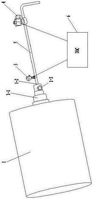
[0019] like figure 1 As shown, an electronically controlled hydrophobic device for a steam dryer includes a steam dryer 1, the steam dryer 1 includes a steam rotary joint 1-1, and the steam rotary joint 1-1 has a drain port 1-2 and a steam inlet 1 -3; the drain pipe 5 communicates with the drain port 1-2 of the steam rotary joint 1-1, and the drain pipe 5 is provided with a temperature transmitter 3 and a control valve 4, the temperature transmitter 3 It is electrically connected with the controller 6, and the control valve 4 is electrically connected with the controller 6 directly or indirectly.

[0020] The controller 6 of the present invention is a digital controller, or an industrial computer. When the control valve 4 is a solenoid valve, the control valve 4 is electrically connected to the controller 6 directly or indirectly. When the control valve 4 is a pneumatic valve, the control valve 4 is electrically connected to the controller 6 indirectly.

[0021] The working...

Embodiment 2

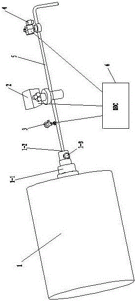
[0025] like figure 2 As shown, the difference between embodiment 2 and embodiment 1 is: an electronically controlled drainage device for a steam dryer, which also includes a water conductivity transmitter 2, and the water conductivity transmitter 2 is arranged on the drainage pipe 5 On the pipeline, and the water conductivity transmitter 2 is electrically connected with the controller 6. The water conductivity transmitter 2 is arranged between the temperature transmitter 3 and the control valve 4 on the pipeline of the drain pipe 5 .

[0026] The working process of embodiment 2: when the steam drying cylinder equipment is just started, the controller 6 controls the control valve 4 to open, and the steam enters the steam drying cylinder through the steam inlet 1-3 of the steam rotary joint 1-1, pushing air, etc. The non-condensable gas and condensed water are discharged through the drain pipe 5 and the control valve 4; the controller 6 receives the data detected by the temper...


PUM


Abstract

The invention relates to a steam cylinder electric control drainage device which comprises a steam cylinder. The steam cylinder comprises a steam rotary connector which is provided with a drain outlet and a steam inlet. The steam cylinder electric control drainage device is characterized by further comprising a temperature transmitter, a control valve, a drain pipe and a controller, the drain pipe is communicated with the drain outlet of the steam rotary connector, the temperature transmitter and the control valve are arranged on a pipeline of the drain pipe, the temperature transmitter is electrically connected with the controller, and the control valve is directly or indirectly electrically connected with the controller. Steam lock can be effectively prevented from being formed, drainage is accurate, and energy conservation and efficiency are achieved.

Description

technical field [0001] The invention belongs to the technical field of textile dyeing and finishing, and in particular relates to an electronically controlled hydrophobic device for printing and dyeing steam drying cylinder equipment. Background technique [0002] At present, printing and dyeing enterprises use a large number of steam dryers to dry fabrics with water, and non-condensable gases such as condensed water and air in the steam dryer will affect the heat exchange efficiency. Therefore, it is necessary to discharge them in time to improve the efficiency of steam equipment. Thermal efficiency, thereby saving steam and reducing fuel consumption. For this reason, equipment heated by steam must be equipped with a steam trap (also known as a water vapor separator) to automatically discharge the continuously generated condensed water and prevent steam leakage. [0003] In the existing technology, the steam dryers of printing and dyeing enterprises use two different metho...

Claims


Application Information

Patent Timeline
Patent Type & Authority Applications(China)
IPC IPC(8): F26B25/00
CPCF26B25/00
Inventor 顾金华刘功
Owner 顾金华
Why Eureka
Try Eureka